5 bt 5 ti, D 100.0, T 5 c 0.0 – Ashcroft GC52 - Rangeable wet/wet Differential Pressure Transmitter User Manual
Page 10
10
k
M
k
M
k
M
k
M
k
M
N ROT
d 0
d i
d Z
d 3
a 100.0
L 10.0
P. 4.00
a 0.0
U SE1
U SE(
U hou
U n
~In
U 10
U 100
U 1000
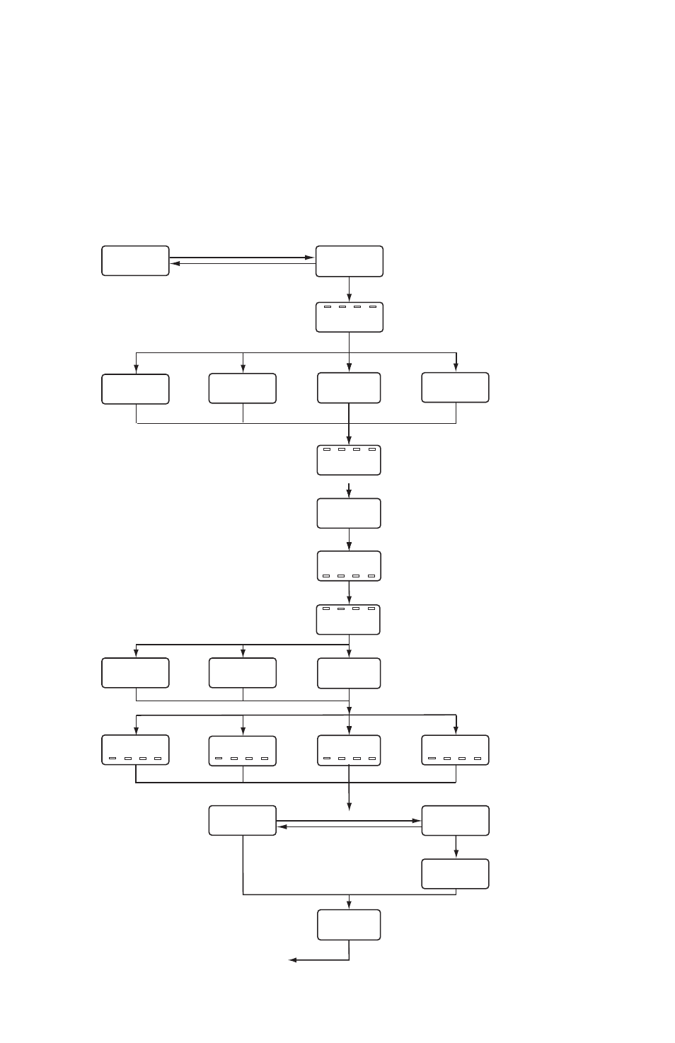
Flow Measurement Mode
(Square Root Extraction Settings)
Refer to
Section 14.3
ባ Flow Measurement / Square Root
Extraction Mode
ተ Maximum Differential
Selection
ቱ Flow Rate
Decimal Point
Position
5 Bt
5 tI
k
22
Display Switch
Setting
k
23
Switch Time
Interval
k
24
Loop Check
Returns to
Setting Mode
ታ Low Cut
ት Output Span Point
ቶ Time Factor
k
M
k
M
k
M
k
M
k
M
k
M
k
M
k
M
D1000.0
ቲ Maximum Momentry
Flow
D 100.0
İ
ĭ
İ
ĭ
İ
ĭ
İ
ĭ
İ
ĭ
t 5
c 0.0
k
21
Flow Rate
Volume Factor
İ
ĭ
İ
ĭ
İ
ĭ
İ
ĭ
k
M
ቴ Output Zero Point
k
22
Flow Measurement Mode (Square Root Extraction) Setting
E.
Loop Check: Use to send a 4-20mA signal meant to simulate applied
pressure, can be accessed either through Pressure Display Mode or Linear
Display Mode. See “Complete Setting Mode Menu”; Loop Check is noted
on the screen with a prefix “
(
”. The display is indicating in actual units and
starts at the zero (4mA) point.
If $ button is pressed, the linear display will auto increment by linkage be-
tween the linear display and the analog output. By continuing to press # but-
ton, auto decrement will occur. Release the button at the desired indication.