0 accuracy: procedures/definitions, Typical calibration chart – Ashcroft 1036 Gauge with 1037 Fitting User Manual
Page 6
6
f.
Gauges showing significant friction error and/or wear of
the movement and linkage.
g.
Gauges having damaged sockets, especially damaged
threads.
h.
Liquid filled gauges showing loss of case fill.
NOTE: ASME B40.100 does not recommend moving gauges
from one application to another. This policy is prudent in that
it encourages the user to procure a new gauge, properly tai-
lored by specification, to each application that arises.
6.0 ACCURACY: PROCEDURES/DEFINITIONS
Accuracy inspection – Readings at approximately five
points equally spaced over the dial should be taken, both
upscale and downscale, before and after lightly rapping the
gauge to remove friction.
A pressure standard with accuracy
at least four times greater than the accuracy of the gauge
being tested is recommended.
Equipment – A finely regulated pressure supply will be required.
It is critical that the piping system associated with the test setup
be leaktight. The gauge under test should be positioned as it will
be in service to eliminate positional errors due to gravity.
Method – ASME B40.100 recommends that known pres-
sure (based on the reading from the pressure standard used)
be applied to the gauge under test. Readings including any
error from the nominal input pressure, are then taken from the
gauge under test. The practice of aligning the pointer of the
gauge under test with a dial graduation and then reading the
error from the master gauge (“reverse reading”) can result in
inconsistent and misleading data and should NOT be used.
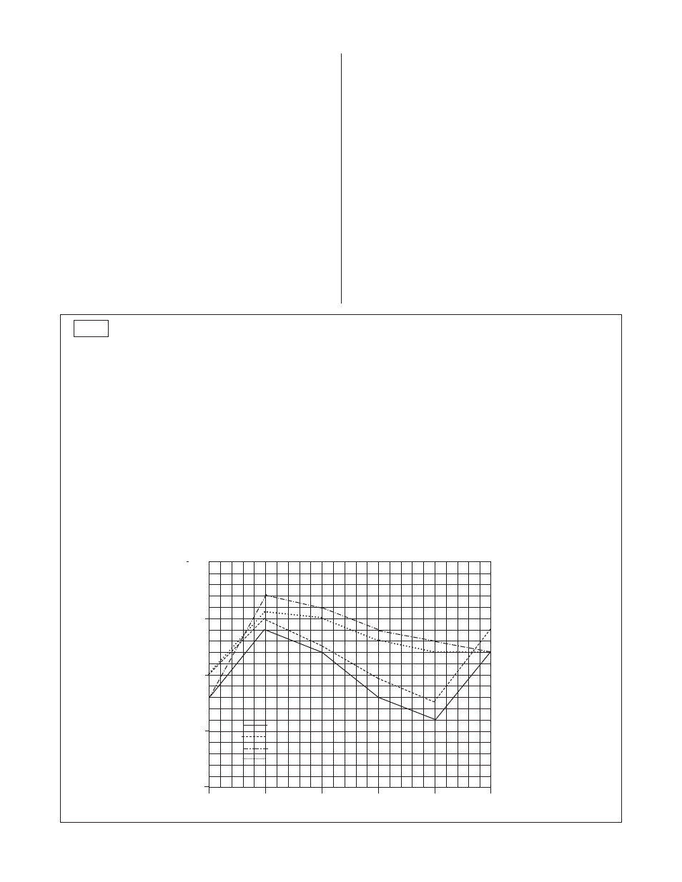
Calibration chart – After recording all of the readings it is
necessary to calculate the errors associated with each test
point using the following formula: ERROR in percent = 100
times (TRUE VALUE minus READING) ÷ RANGE. Plotting
the individual errors (Figure 1) makes it possible to visualize
the total gauge characteristic. The plot should contain all four
curves: upscale – before rap; upscale – after rap; downscale
– before rap; downscale – after rap. “Rap” means lightly tap-
ping the gauge
before reading to remove friction as
described in ASME B40.100.
Referring to Figure 1, several classes of error may be seen:
Zero – An error which is approximately equal over the entire
scale. This error can be manifested when either the gauge is
TYPICAL CALIBRATION CHART
INDICATED VALUE (PSI)
True Value –
Increasing –
Increasing –
Decreasing –
Decreasing –
PSI
Without RAP
With RAP
Without RAP
With RAP
0
–.4
0
–.4
0
40
+.8
+1.0
+1.4
+1.1
80
+.4
+.5
+1.2
+1.0
120
–.4
–1.0
+.8
+.6
160
–.8
–.5
+.6
+.4
200
+.4
+.8
+.4
+.4
ERROR (% OF FULL SCALE)
True Value –
Increasing –
Increasing –
Decreasing –
Decreasing –
% of Range
Without RAP
With RAP
Without RAP
With RAP
0
–.20
0
–.20
0
20
+.40
+.50
+.70
+.55
40
+.20
+.25
+.60
+.50
60
–.20
–.05
+.40
+.30
80
–.40
–.25
+.30
+.20
100
+.20
+.40
+.20
+.20
1.0
0.5
0.0
–0.5
–1.0
0
20
40
60
80
100
% of Range
◆
◆
◆
◆
■
■
■
■
●
●
●
●
●
●
▲
▲
▲
▲
▲
▲
▲ ▲
upscale – without rap
● ●
upscale – with rap
◆ ◆
downscale – without rap
■ ■
downscale – with rap
E
rr
o
r
(%
o
f
F
u
ll
S
c
a
le
)
FIG. 1
- 1009 - Stainless Steel Pressure Gauge 1008S/SL - Stainless Steel Pressure Gauge 1008S - Stainless Steel Pressure Gauge 1189 - Low Pressure Bellows Gauge 1188 - Low Pressure Bellows Gauge 1187 - Low Pressure Bellows Gauge 1150H - Reid Vapor Gauge 1122 - Industrial Gauge 1220 - Industrial Gauge 1017 - Industrial Gauge 1220 - Receiver Gauges 1017 - Receiver Gauges 1010 - Receiver Gauges 1009 - Receiver Gauges 1220 - Refrigeration Gauges 1017 - Refrigeration Gauges 1010 - Refrigeration Gauges 1009 - Refrigeration Gauges 1220 - Hydraulic Gauges 1017 - Hydraulic Gauges 1010 - Hydraulic Gauges 1009 - Hydraulic Gauges 1010 - Industrial Gauge 2462 - Duragauge® Pressure Gauge 1379 - Duragauge® Pressure Gauge 1377 - Duragauge® Pressure Gauge 2462 - Receiver Gauges 1377 - Receiver Gauges 1379 - Receiver Gauges 1279 - Receiver Gauges 1259 - Pressure Gauge 1082 - Pressure Test Gauge