Ashcroft, Type 1188 bellows gauge calibration procedure – Ashcroft 1036 Gauge with 1037 Fitting User Manual
Page 11
11
© Ashcroft Inc., 250 E. Main St., Stratford, CT 06614-5145, Tel: 203-378-8281, Fax: 203-385-0499, www.ashcroft.com
All sales subject to standard terms and conditions of sale.
I&M008-
10173-3/10 (1188)
ASHCROFT
®
Type 1188 Bellows Gauge
Calibration Procedure
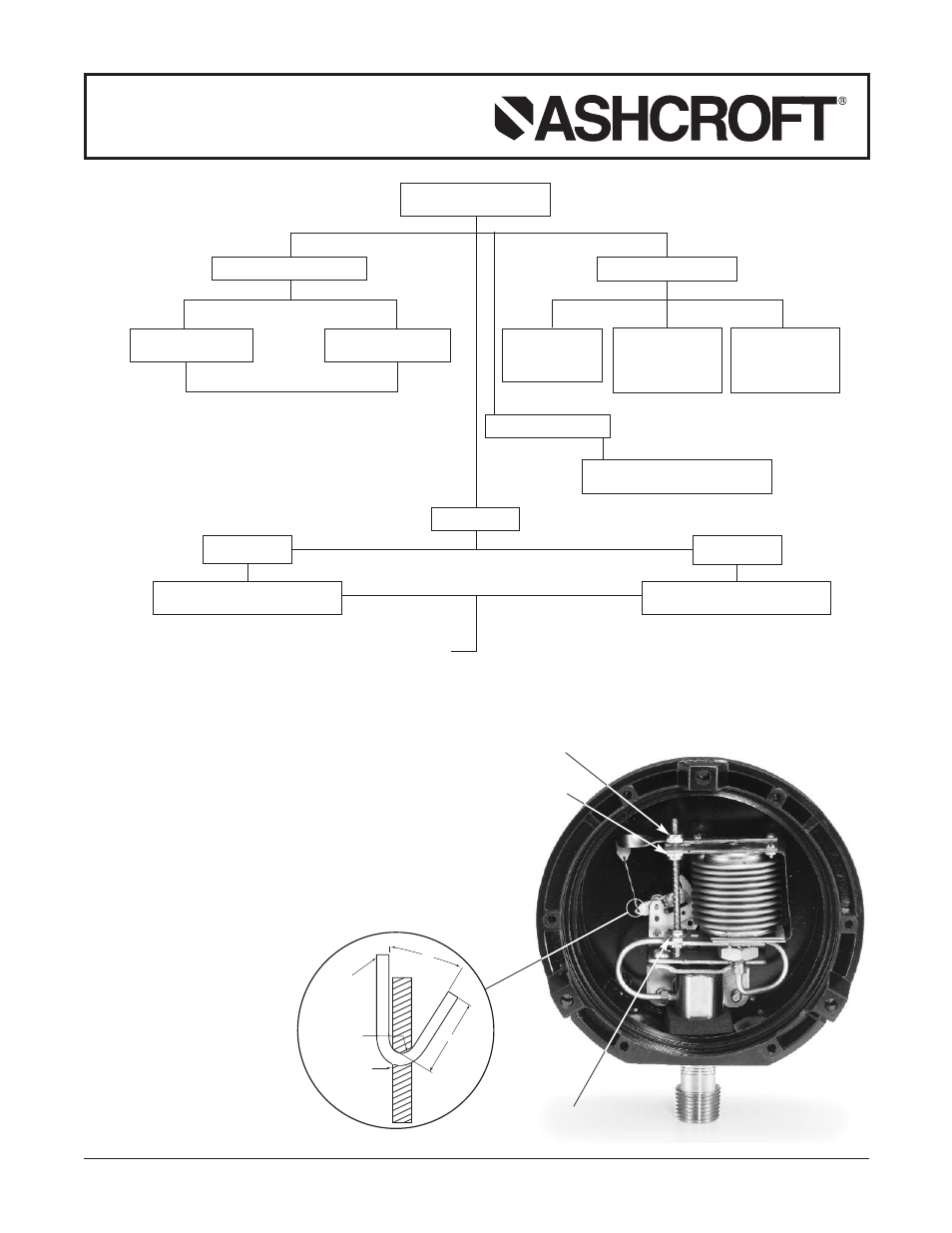
CALIBRATION & TROUBLE
CORRECTION DIAGRAM
POINTER JUMPING
SLUGGISH MOVEMENT
NON LINEAR
STICKY PARTS
Clean all bearings
and gear teeth
RANGE SPAN ADJUSTMENT
RANGE TOO SHORT
Adjust slide “S” inward
RANGE TOO LONG
Adjust slide “S” outward
LOOSE HAIRSPRING
Remove backlash by
disengaging pinion &
rotate to tighten
COUNTER BALANCE
RUBBING
Bend if necessary to
clear socket in travel
NOTE: After adjusting range span, set both movement stops.
Set the underload stop so that the pointer will stop at
zero. Set the overload stop so that the pointer will pass
the maximum range approximately 5˝.
NOTE:
After adjusting span re-zero pointer by removing from
pinion and re-assembling at the proper dial mark.
NOTE: To increase or decrease angle “A,“ bend tip inward or outward as
required. Doing this may run the movement segment off the pin-
ion. This can be corrected by cutting off one end off the link “E”
decreasing its length, or makin a new length from .032 dia. phos.
bronze wire.
Caution: When reproducing link end, follow figure 44 very closely.
this will prevent too much play, or, binding in operation.
REF: Replacing System Bellows
After assembling bellows to the gauge socket securely, subject sys-
tem to 30 psi for five minutes, allowing bellows to travel approxi-
mately 1/8˝ against the overload stop. After this, heat treat system for
15 hours at 250°F, this procedure is necssary to prevent gauge drift.
TIGHT HAIRSPRING
Loosen by disengaging pinion & rotate
NON LINEAR
FIRST 3RD.
NON LINEAR
LAST 3RD.
ADJ. ANGLE OF PULL
BY INCREASING ANGLE “A”
ADJ. ANGLE OF PULL
BY DECREASING ANGLE “A”
STOP LOCKING
SCREWS
OVERLOAD
STOP
SLIDE AND LINK (angle “A”)
Enlarged view of slide and link
UNDERLOAD
STOP
1/8
60°
.020 R
E
(LINK)
S
(SLIDE)
- 1009 - Stainless Steel Pressure Gauge 1008S/SL - Stainless Steel Pressure Gauge 1008S - Stainless Steel Pressure Gauge 1189 - Low Pressure Bellows Gauge 1188 - Low Pressure Bellows Gauge 1187 - Low Pressure Bellows Gauge 1150H - Reid Vapor Gauge 1122 - Industrial Gauge 1220 - Industrial Gauge 1017 - Industrial Gauge 1220 - Receiver Gauges 1017 - Receiver Gauges 1010 - Receiver Gauges 1009 - Receiver Gauges 1220 - Refrigeration Gauges 1017 - Refrigeration Gauges 1010 - Refrigeration Gauges 1009 - Refrigeration Gauges 1220 - Hydraulic Gauges 1017 - Hydraulic Gauges 1010 - Hydraulic Gauges 1009 - Hydraulic Gauges 1010 - Industrial Gauge 2462 - Duragauge® Pressure Gauge 1379 - Duragauge® Pressure Gauge 1377 - Duragauge® Pressure Gauge 2462 - Receiver Gauges 1377 - Receiver Gauges 1379 - Receiver Gauges 1279 - Receiver Gauges 1259 - Pressure Gauge 1082 - Pressure Test Gauge