5 connecto rs and connections – Videotec SM82A User Manual
Page 48
Page 10
MNVCSM42A_0408
3.5 Connecto rs and connections
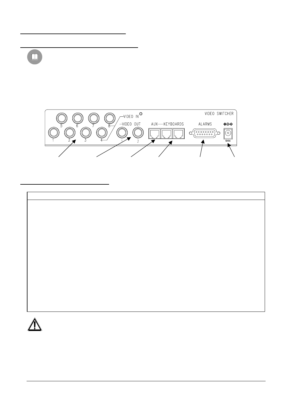
3.5.1 Connectors on the back of the matrix
The back of the SM42A / SM82A matrix has:
• 1 x 15 pin connector for connecting alarm contacts, relay contacts, VCR trigger and external alarm reset
• 2 x RJ-11 connectors for connecting the keyboards
• 1 x RJ-11 connector for connecting the telemetry receivers or multiplexers
• 1 jack connector for the power supply
• 2 BNC output video connectors
• 4/8 BNC input video connectors
3.5.2 Pin configu ration for DB15
Pin
Connection
Use
1
Alarm input 1
Alarms
2
Alarm input 2
Alarms
3
Alarm input 3
Alarms
4
Alarm input 4
Alarms
5
Alarm input 5
Alarms
6
Alarm input 6
Alarms
7
Alarm input 7
Alarms
8
Alarm input 8
Alarms
9
GND
GND (alarms/ VCR trigger / reset Alarms)
10
NO Relay
Peripherals
11
Common Relay
Peripherals
12
VCR Trigger
Video cassette recorder
13
Reset alarms
Reset alarms
14
GND
GND (alarms/ VCR trigger / reset Alarms)
15
GND
GND (alarms/ VCR trigger / reset Alarms)
Alarms 5-6-7-8 are only available on the SM82A model matrix.
Input video
Output
video
Aux Line
Keyboard
inputs
Alarms, VCR trigger
And relè
Power supply
Jack