Videotec SM82A User Manual
Page 47
Page 9
MNVCSM42A_0408
3.4.2.2 Selecting the protocol for communication with the keyboards
Switch off the matrix by disconnecting the power supply jack
• Remove the screws fastening down the cover and open the matrix, following the instructions given in section 3.4.1
• Find and set the dip-switches according to the table below
• Close the cover and fasten it with the screws
• Connect the power supply jack to switch the matrix back on.
Note: all changes to the dip-switches are recognised when the matrix is restarted
Dip switch
1
2
3
4
Protocol and baud rate
Connected keyboards
OFF
OFF
OFF
OFF
OFF
OFF
OFF
OFF
OFF
OFF
ON
ON
OFF
ON
OFF
ON
Macro, 38400 baud (*)
Macro, 19200 baud
Macro, 9600 baud
Macro, 1200 baud
New series keyboards:
DCJ, DCK, DCTEL, DCBD, DCT, DCIR
OFF
OFF
ON
ON
OFF
OFF
OFF
ON
Linxs, 9600 baud
Linxs, 1200 baud
Linxs series keyboards:
LXRPK12, LXRPK23, LXRPRC36
OFF
OFF
ON
ON
ON
ON
OFF
ON
Videotec switchers, 9600
baud
Videotec switchers, 1200
baud
Previous series keyboards:
SWC4, SWC8, DCMT8 with interface
ON
ON
OFF
OFF
OFF
OFF
OFF
ON
Videotec OSM, 9600 baud
Videotec OSM, 1200 baud
Previous series keyboards:
DCS2, KEYPLUS, SWC16 with interface
ON
OFF
ON
OFF
Videotec SW328, 9600 baud
Previous series keyboard: DCS3
ON
ON
ON
ON
ON
OFF
ON
ON
ON
ON
ON
OFF
OFF
ON
ON
ON
OFF
ON
OFF
ON
Invalid configurations
-
(*)Default configuration
3.4.3 Inserting th e load on the AUX line
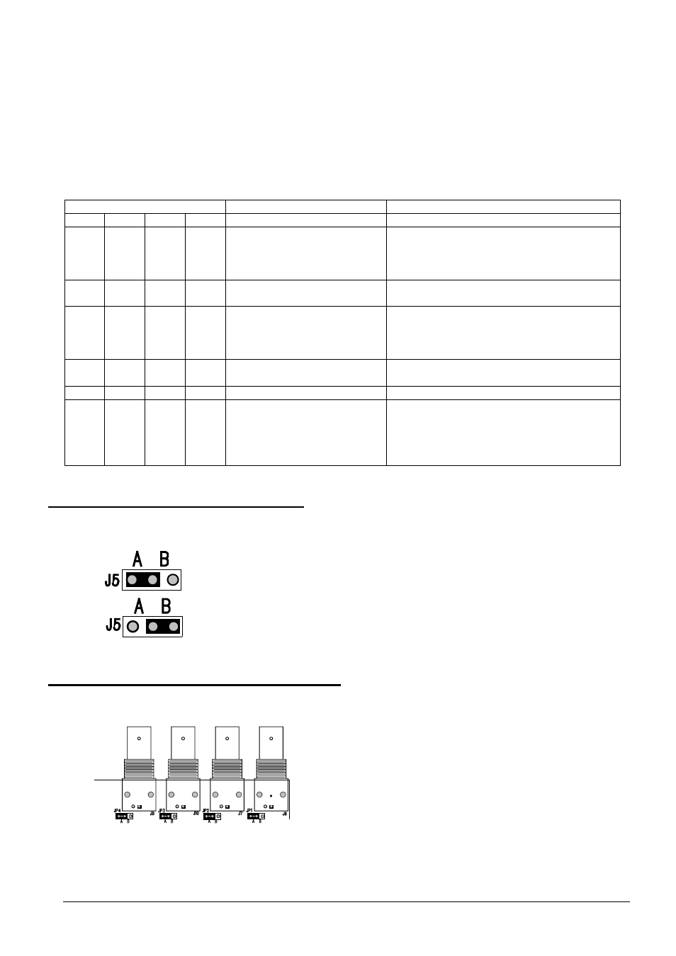
To insert/disconnect the 120 Ohm load on the RS485 AUX line, position jumper J5 as shown in the
diagram:
3.4.4 Setting 75 O hm video input termination
It’s possible to remove the 75 Ohm video input termination putting the corresponding jumper into position B.
Example: all input with 75 Ohm load inserted
Jumper J5 with load connected (position A)
Jumper J5 with load disconnected (position B)