6 assembling and installing, 1 installation, 1 connections – Videotec UPTIRPS120 User Manual
Page 5
EN - English - I
nstruc
tions manual
3
g
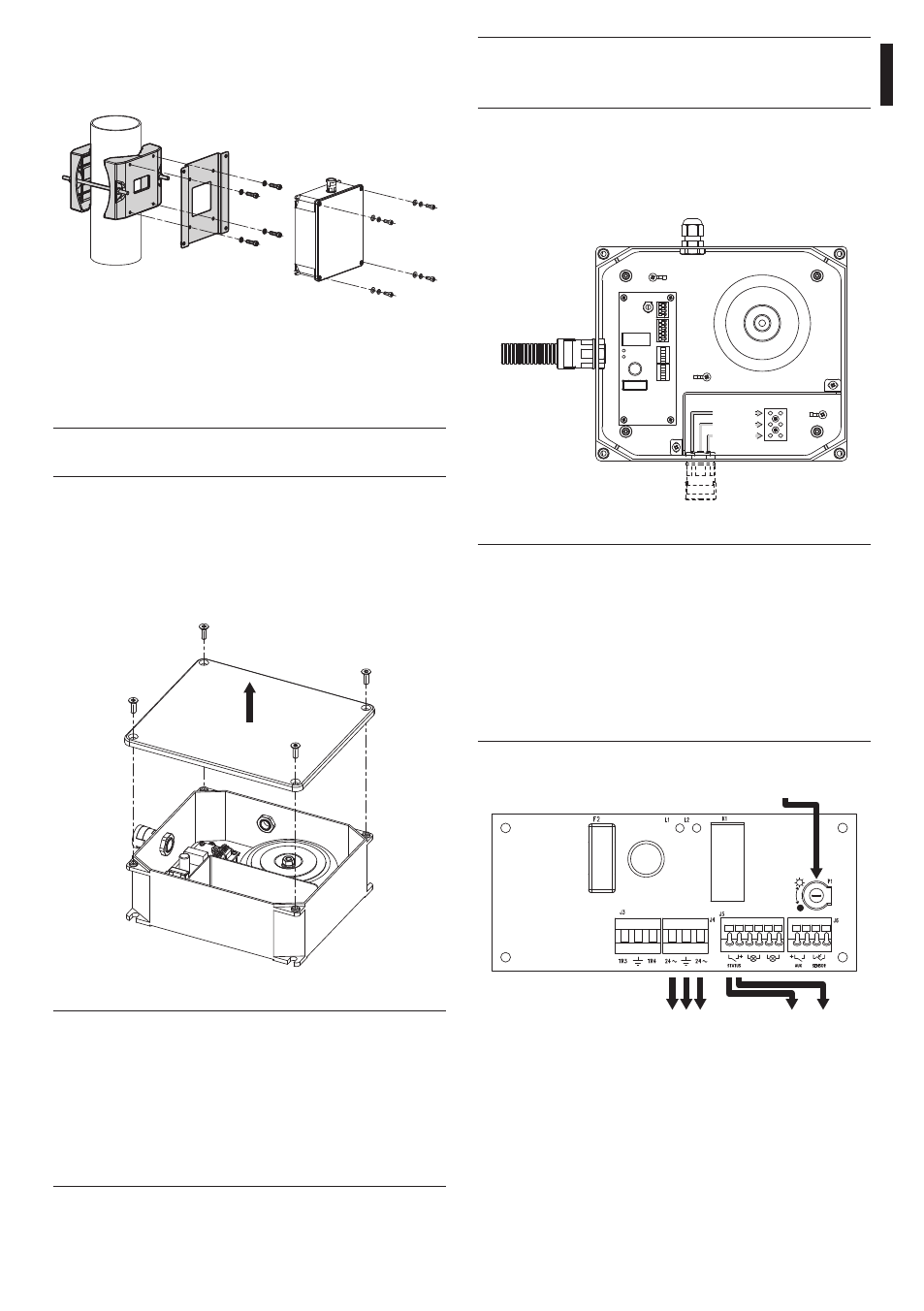
Always make the base connections with the
power supply disconnected and the circuit-
breaker open.
Connect the power supply cables to the electric
network, according to that indicated in the figure.
Use cables with section equal to at least 2mm²
(AWG 14).
a
Line
Line
Fig. 05
h
Earth cable should be about 10mm longer
than the other two, so that it will not be
disconnected accidentally if the cable is
stretched or pulled. The power supply
cable should also be covered by the silicone
sheath (01) supplied for this purpose, and
fastened with the corresponding tie (02).
Furthermore, all signal cables must be
grouped together by means of a strap (03).
J4 - P&T power
supply output
J5 - Day/Night
status
Sensitivity
adjustment trimmer
Fig. 6
Connec the DAY/NIGHT output, identified by the
STATUS indication to connector J5, at pan & tilt LNO
input. Connect the 24V(J4) power supply output
to the relative power supply connector (J6) of the
ULISSE IR360 positioning unit. Use cables with section
of 1.5mm² (AWG 16).
The box can be also mounted on the pole mount
adapter PTCC1 using the adapter OIRPSCPA available
as accessory.
Fig. 03
6 Assembling and
installing
h
Only specialised personnel should be
allowed to assemble and install the device.
6.1 Installation
6.1.1 Connections
Open the watertight box, taking care not to damage
the seals.
Fig. 04
h
The building must be equipped with a
20A maximum bipolar protection circuit
(magneto thermal), that must include a
bipolar automatic-type circuit breaker,
which must also envisage earth fault
current protection (magneto-thermal +
differential) with minimum distance of
3mm between contacts.