Connection/installation – Kenwood DDX4025BT User Manual
Page 51
PRK SW
REVERSE
ENGLISH
51
CONNECTION/INSTALLATION
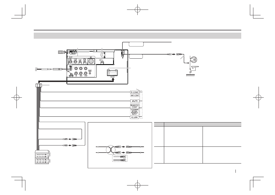
CONNECTION/INSTALLATION
Connection
R
Connecting wires to terminals
See page 52.
See page 53.*
1
USB terminal: See
page 52.
Connect the aerial cord
to the aerial terminal.
10 A fuse
Connect to the vehicle’s reverse lamp harness when
using the optional rear view camera.
Connect to the vehicle’s parking
brake detection switch harness.
• For best safety, be sure to
connect the parking sensor.
To the power control terminal when using the optional power amplifier or to
the aerial control terminal in the vehicle.
To the terminal that is grounded when either the telephone rings or during
conversation. (To connect the Kenwood navigation system, consult your
navigation manual.)
To use the steering wheel remote control feature, you need an exclusive
remote adapter (not supplied) matching your car is required.
To car light control switch
Purple with white stripe
(Reverse sensor wire)
Light green
(Parking sensor wire)
3
1
Blue with white stripe (Power control/aerial control wire)
Brown (Mute control wire)
Light blue with yellow stripe (Steering remote control wire)
Orange with white stripe (Dimmer control wire)
*
1
Only for DDX4025DAB/DDX4025BT/DDX4055BT.
*
2
If no connections are made, do not let the cable come
out from the tab.
Connector A
Connector B
Pin
Color and functions of Connector A and B
A4
Yellow
Battery
A5
Blue/White
Power control
A6
Orange/White
Dimmer
A7
Red
Ignition (ACC)
A8
Black
Ground connection
B1/B2 Purple ª / Purple/Black ·
Right speaker (rear)
B3/B4 Gray ª / Gray/Black ·
Right speaker (front)
B5/B6 White ª / White/Black ·
Left speaker (front)
B7/B8 Green ª / Green/Black ·
Left speaker (rear)
Red
(Ignition wire)
Unit
Yellow
(Battery wire)
Vehicle
Red (A7)
Yellow (A4)
Default wiring
Connecting the ISO connectors on some VW/
Audi or Opel (Vauxhall) automobiles
You may need to modify the wiring of the
supplied wiring harness as illustrated below.
*
2
Yellow (Battery wire)
Red (Ignition wire)
Red (A7)
Yellow (A4)
DDX_Entry_E.indb 51
DDX_Entry_E.indb 51
2013/10/30 13:54
2013/10/30 13:54