High Country Tek emc-1V User Manual
Page 10
Part No:-
021-00351 Rev 1.0
emc-1P & emc-1V e-Fan System Controller User Guide
Page 10
e-Fan Cooling System Controllers
with J1939 Interface
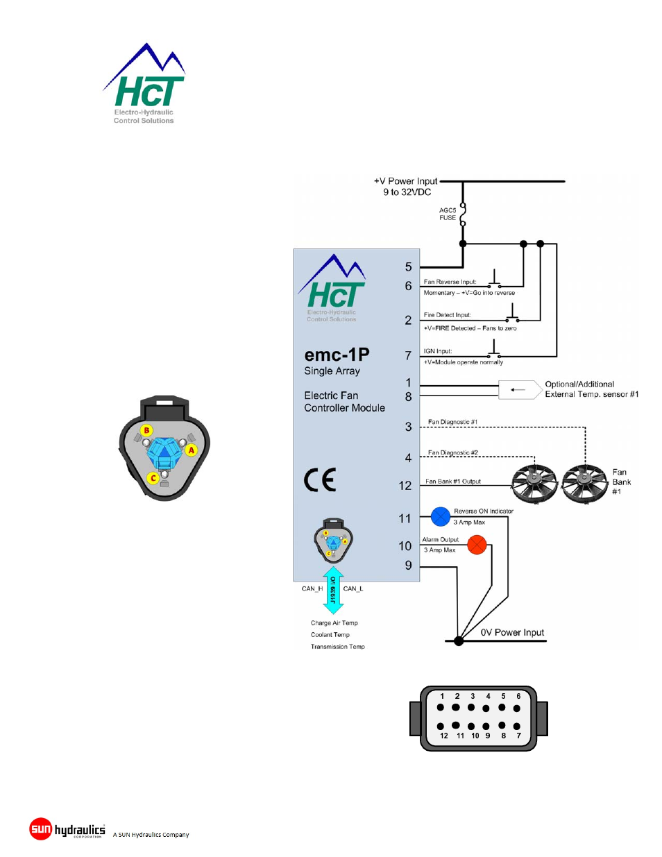
emc-1P Connection Information
NOTE: Controller MUST have in‐line fuse
fitted by
user in the +V Power Input for system
protection.
SAE J1939 Connections
Pin A CAN_Hi (SAE J1939)
Pin B CAN_Low (SAE J1939)
Pin C No connection
Pin 1 ................. Sensor #1 +signal input
Pin 2 ................. Fire detect input
Pin 3 ................. Fan #1 Diagnostic input
Pin 4 ................. Fan #2 Diagnostic input
Pin 5 ................. +Volts 9-32VDC input
Pin 6 ................. Reverse fan input (momentary)
Pin 7 ................. Ignition ON input
Pin 8 ................. Sensor #1 common
Pin 9 ................. Power supply return (GND)
Pin 10 ............... Alarm output (3A max sourcing)
Pin 11 ............... Reverse output (3A max sourcing)
Pin 12 ............... 0-100% PWM e-fan output