6 wiring diagram, 7 connection conditions, 6 wiring diagram 5.5.14.7 connection conditions – ARI Armaturen ARI-PREMIO User Manual
Page 49
0040501000 4511
Page 49
Operating and installation instructions
Thrust actuator ARI-PREMIO
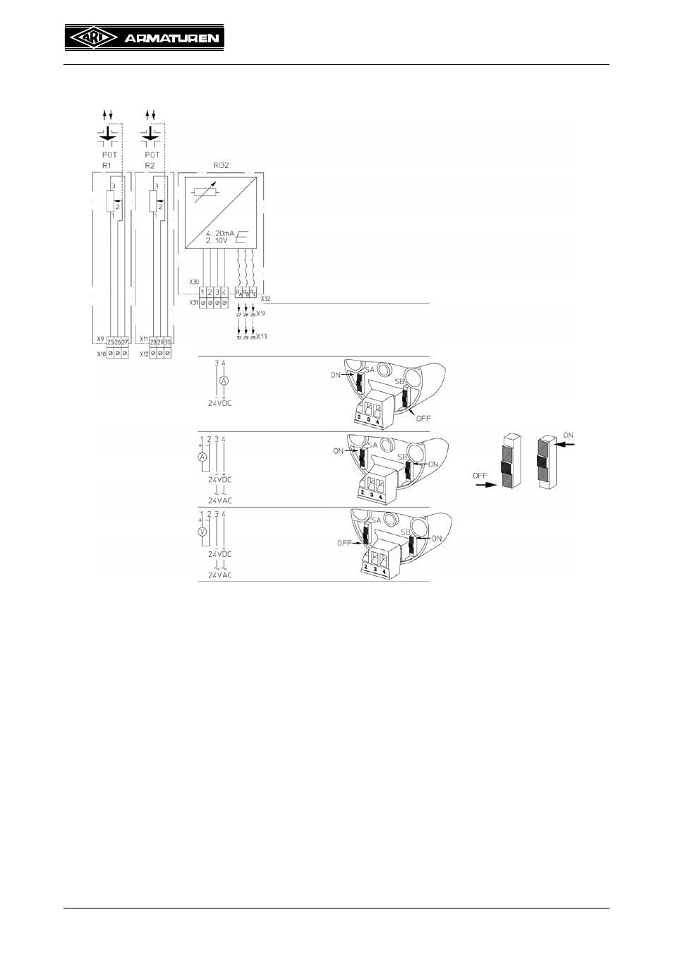
5.5.14.6 Wiring diagram
Fig. 29
5.5.14.7 Connection conditions
The electrical connections are joined to position indicator RI32 by series disconnect
terminals. The connection to the potentiometer is made by a cable.
Position indicator RI32 is connected by a potentiometer (R1 or R2) built into the ARI-
PREMIO.
When the valve is shut approx. 0 ohm are applied between Rb and Rc.
Appropriate conductor cross-sections for terminal connections are 0.2 to 2.5 mm
2
.
To achieve electromagnetic compatibility is recommended that shielded conductors be
used for longer routings.
Please request technical information direct from ARI-Armaturen.
Attention:
Do not connect terminal 2 and
terminal 3.
With a potential shift, the position
indicator RI32 might be destroyed.
or
Potentiometer connection optionally
with R1 or R2 potentiometers
from 100 Ohm to 20 kOhm
Two-wire connection
(current loop)
4...20mA
24V DC
Four-wire connection
4...20mA
24V DC and AC
Four-wire connection
2...10V
24V DC and AC