14 electronic position indicator ri32, 1 useful range of the linear motion potentiometer – ARI Armaturen ARI-PREMIO User Manual
Page 46
Page 46
0040501000 4511
Operating and installation instructions
Thrust actuator ARI-PREMIO
5.5.14 Electronic position indicator RI32
The RI32 electronic indicator transforms a resistance change into a 4...20mA or 2...10V
standardised control signal.
The RI32 position indicator can be operated by 24V DC voltage or 24V AC voltage.
It is possible to link into a current loop without an additional power supply.
5.5.14.1 Useful range of the linear motion
potentiometer
Linear motion potentiometers R1 or R2 are
connected in a three-conductor connection.
Here the RI32 position indicator is also suitable
for conductive plastic potentiometers.
The diagram on the right will help when
adjusting the RI32 position indicator to the
stroke distance of the linear motion
potentiometer.
It is important that the mechanical stroke
distance of the control actuator is smaller than
the stroke distance of the linear motion
potentiometer.
Fig. 26: Linear motion potentiometer
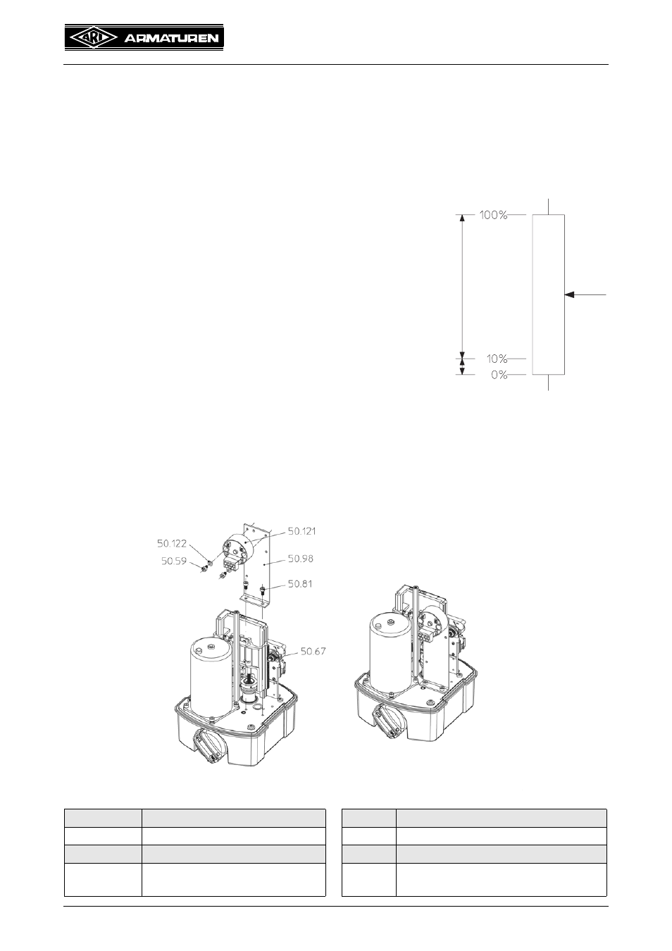
5.5.14.2 Installing the RI32 electronic position indicator in the PREMIO
- The RI32 position indicator is fitted to the ARI-PREMIO as illustrated.
- Screw fixing bracket (pos. 50.98) to gearbox cover plate with head cap screw (pos. 50.81).
- Then fit position indicator (pos. 50.121) to fixing bracket (pos. 50.98) with the head cap
screws (pos. 50.59) and washers (pos. 50.122).
Fig. 27: Option RI32 ARI-PREMIO 2,2 - 5 kN
Pos.
Designation
Pos.
Designation
50.59
Head cap screw M4 x 6
50.98
Fixing bracket
50.67
Potentiometer
50.121 Position indicator RI32
50.81
Head cap screw
DIN EN ISO 4762 - M4x8
50.122 Washer 4.3
adjustable
adjustable
slope span setting range
zero point setting range