4 electrical connection, 1 wiring diagram ari-premio 2.2 - 5 kn – ARI Armaturen ARI-PREMIO User Manual
Page 21
0040501000 4511
Page 21
Operating and installation instructions
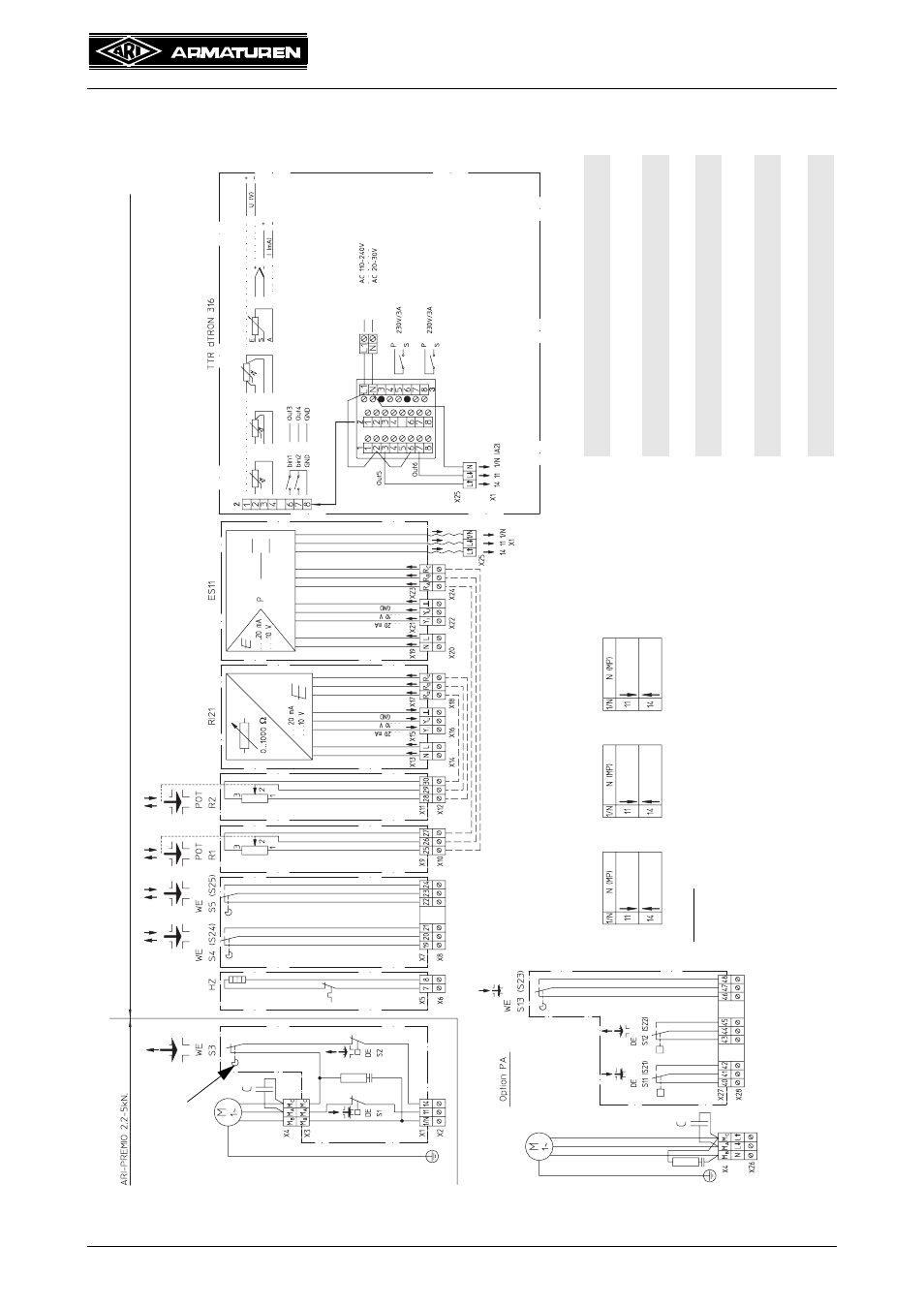
Thrust actuator ARI-PREMIO
5.4 Electrical connection
5.4.1 Wiring diagram ARI-PREMIO 2.2 - 5 kN
Fig. 9
ac
ces
so
rie
s
HZ
He
atin
g res
ist
or
DE
To
rq
ue s
w
itch
WE (S3)
Tr
av
el
switc
h for t
rave
ling
the
stro
ke d
ist
anc
e
in re
tract
ing
direc
tion
RI 21
Elec
troni
c po
sit
ion
indi
cat
or
ES 1
1
Elec
troni
c po
sit
ion
con
troll
er
NA
Low-vo
ltag
e c
onne
cti
on b
oard,
ze
ro
pot
enti
al
PA
Stand
ard-v
olta
ge c
onn
ect
ion
board
,
zero
pot
enti
al
POT
Poten
tiomete
r
WE
Tr
avel
switch, zero p
oten
tial
TTR
Elec
troni
c te
mpe
ra
ture-c
ontro
ller
dTRON 31
6
Opti
on NA
:
sa
me
des
ign
bu
t no
RC c
ircui
t
and s
w
itch
es
wi
th go
ld c
on
tact
s
(Switc
hin
g ca
pac
ity
0.1
A, 4-30
VDC)
clo
se
d
open
A-AB op
en
B-
AB
o
pe
n
AB-B op
en
AB
-A o
pen
Straight through
valve
3-way v
al
ve
with diverting
plu
g
3-way valve
with m
ixing
plug
W
ire connectio
ns of the
different valve
ty
pes
sta
nda
rd
In
pu
t resista
nce
the
rmo
me
ter
Te
le
-
Th
er
m
o-
Vo
lta
ge
Cu
rren
t
Bi
na
ry
in
pu
t
Bin
ar
y
ou
tp
ut
Log
ic
12
V
altern
ativ to
23
0V
/3
A Bi
na
ry
ou
tp
ut
(O
ut
1)
23
0V/
3A Bi
na
ry out
pu t
(O
ut
2)
Out
put
to
the
act
ua
tor
tran
sm
itter
el
em
en
t
0(4)...
20
mA
0(
2)...1
0V
Vo
ltag
e
and
p
ow
er
su
pp
ly
v
ol
ta
ge a
re e
qu
al
bi
na
ry in
pu
ts
bi
n1
an
d b
in2
po
wer
su
pp
ly
Tr
ip
c
am
a
s
accesso
ries tr
ip slid
e