0 basic calibration – Red Lion ITMA User Manual
Page 6
6
1 2 3 4 5 6 7
9
8
10
ON
1 2 3 4 5 6 7
9
8
10
ON
1 2 3 4 5 6 7
9
8
10
ON
1 2 3 4 5 6 7
9
8
10
ON
1 2 3 4 5 6 7
9
8
10
ON
2
1
ON
4
3
5 6 7 8 9 10
ON
3
1 2
5
4
6 7 8 9 10
12 to 42 VDC
Power Supply
±
4 to 20 mA
A
Indicator
Current Display
POWER/
OUTPUT
M2068B
+
4
5
-
6
Thermometer
+
TC
-
1 2
3
Source
+ -
Precision
Millivolt
Adjustable
ITMA
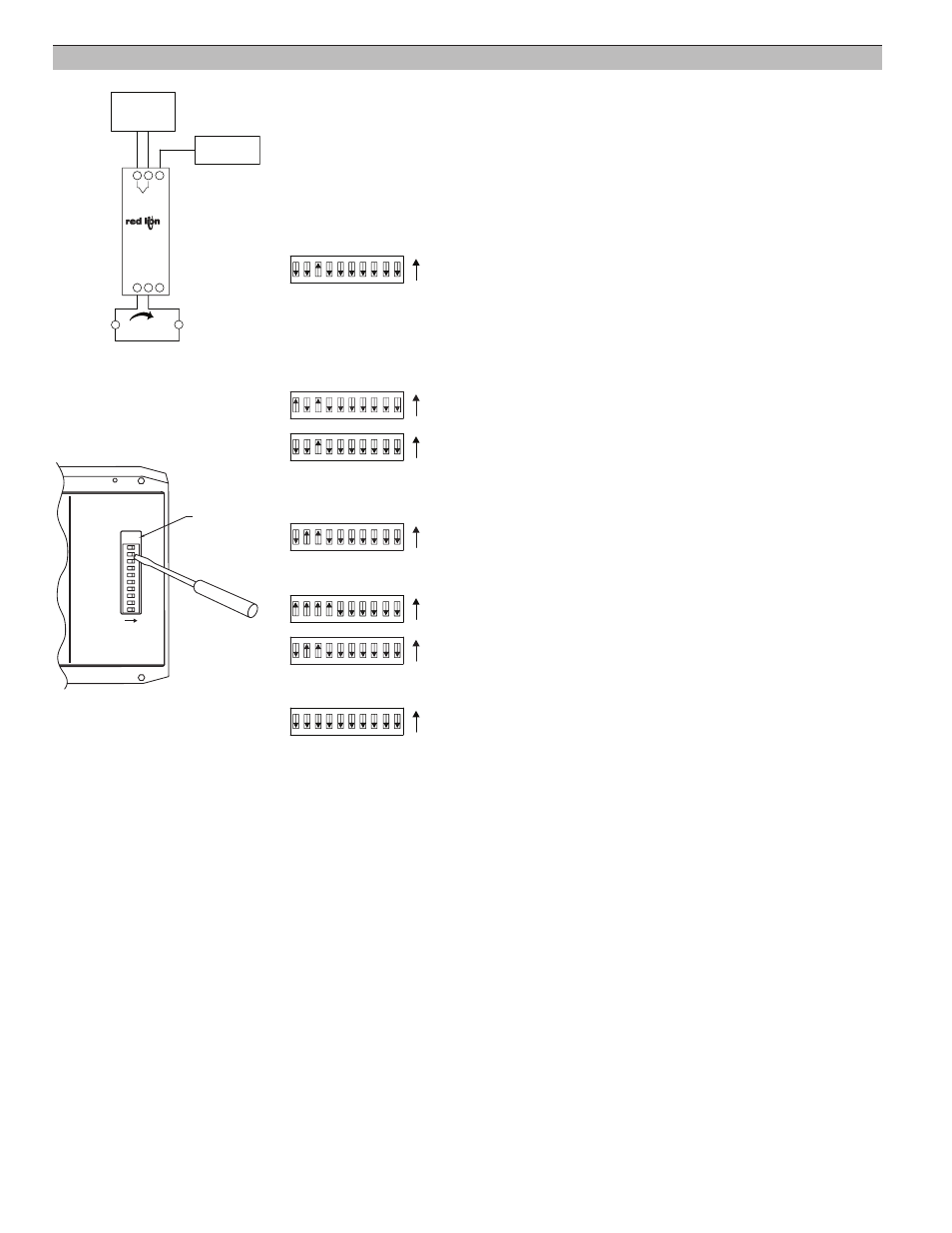
Basic Calibration Wiring
Step 4.1
Steps 4.3 to 4.15
Step 4.16
Step 4.17
Step 4.18
4.0 Basic Calibration
The Basic Calibration should only be performed with an ambient temperature
between 21°C and 29°C. The Basic Calibration was performed on the unit at the
factory and generally does not need to be done again. This procedure initializes the
unit by calibrating the input, and the Ice Point Compensation. The Basic Calibration
should be performed only if a condition exists as described in the “Calibration
Malfunction” section. After completion of this calibration, the unit needs to be scaled
in Field Calibration. The Basic Calibration procedure is described below.
Note: To abort this calibration and reset to the previous settings, set the BASIC CAL
switch OFF prior to the final setting of the OUTPUT CAL switch (Step 4.17) and
turn off power for 5 seconds. Then turn on power and the previous settings will be
loaded.
4.1 Connect a precision mV source with an accuracy of 0.02% to Terminal #1 (TC+
Input) and Terminal #2 (TC- Input). Set the ICE PT EN/DIS switch (#4), RANGE
(#9 ), TYPE (#6, #7, and #8), OUTPUT CAL (#1), and FIELD CAL (#2)
switches OFF. Set the BASIC CAL switch (#3) ON.
4.2 Apply power and allow a 30 minute warm-up period. [Current goes to 3.5 mA
(nominal)]
4.3 Set the OUTPUT CAL switch (#1) ON and then OFF.
4.4 Input -9 mV and wait 5 seconds.
4.5 Set the OUTPUT CAL switch (#1) ON and then OFF.
4.6 Input 6 mV and wait 5 seconds.
4.7 Set the OUTPUT CAL switch (#1) ON and then OFF.
4.8 Input 22 mV and wait 5 seconds.
4.9 Set the OUTPUT CAL switch (#1) ON and then OFF.
4.10 Input 41mV and wait 5 seconds.
4.11 Set the OUTPUT CAL switch (#1) ON and then OFF.
4.12 Input 63 mV and wait 5 seconds.
4.13 Set the OUTPUT CAL switch (#1) ON and then OFF.
4.14 Input 77 mV and wait 5 seconds.
4.15 Set the OUTPUT CAL switch (#1) ON and then OFF.
4.16 Ice Point Calibration.
a. If ice point calibration is not desired, go to step 4.17.
b. To Enable ice point calibration, set the FIELD CAL switch (#2) ON.
1. Connect a precision thermometer (accuracy of 0.1°C) to the unused
terminal beside the TC Input terminals.
2. Allow 5 minutes for the temperature to equalize.
3. Using the temperature indicated by the precision thermometer, input an
equivalent 1 mV/°C signal to the TC Input terminals.
4.17 Set the OUTPUT CAL switch (#1) ON and then OFF.
4.18 Set the BASIC CAL switch (#3) and FIELD CAL switch (#2) OFF. [Current
increases to 3.6 mA (nominal) or more]
4.19 Perform a Field Calibration. (See Section 1.0)
TEST
OUTPUT CAL
FIELD CAL
BASIC CAL
ICE PT EN/DIS
OPEN SEN DN/UP
TC TYPE
TC TYPE
TC TYPE
RANGE
RANGE
DIP SWITCH SETTINGS:
ON = 1
OFF = 0
M2069A
1
2
4
5
6
7
8
9
10
ON
Test
Pad
RED LION CONTROLS
YORK, PA.
MADE IN U.S.A.
MODEL ITMA