Input and power/output connections – Red Lion ITMA User Manual
Page 3
3
5. In extremely high EMI environments, the use of external EMI suppression
devices such as Ferrite Suppression Cores for signal and control cables is
effective. The following EMI suppression devices (or equivalent) are
recommended:
Fair-Rite part number 0443167251 (RLC part number FCOR0000)
Line Filters for input power cables:
Schaffner # FN2010-1/07 (Red Lion Controls # LFIL0000)
6. To protect relay contacts that control inductive loads and to minimize radiated
and conducted noise (EMI), some type of contact protection network is
normally installed across the load, the contacts or both. The most effective
location is across the load.
a. Using a snubber, which is a resistor-capacitor (RC) network or metal oxide
varistor (MOV) across an AC inductive load is very effective at reducing
EMI and increasing relay contact life.
b. If a DC inductive load (such as a DC relay coil) is controlled by a transistor
switch, care must be taken not to exceed the breakdown voltage of the
transistor when the load is switched. One of the most effective ways is to
place a diode across the inductive load. Most RLC products with solid
state outputs have internal zener diode protection. However external diode
protection at the load is always a good design practice to limit EMI.
Although the use of a snubber or varistor could be used.
RLC part numbers: Snubber: SNUB0000
Varistor: ILS11500 or ILS23000
7. Care should be taken when connecting input and output devices to the
instrument. When a separate input and output common is provided, they
should not be mixed. Therefore a sensor common should NOT be connected
to an output common. This would cause EMI on the sensitive input common,
which could affect the instrument’s operation.
Visit RLC’s web site at http://www.redlion.net/Support/InstallationConsiderations.
html for more information on EMI guidelines, Safety and CE issues as they
relate to Red Lion Controls products.
INPUT AND POWER/OUTPUT CONNECTIONS
Input
When connecting the thermocouple, be certain that the connections are clean
and tight. The negative thermocouple lead is connected to Terminal #2 (TC-)
and the positive lead is connected to Terminal #1 (TC+). If the thermocouple
probe cannot be connected directly to the module, thermocouple wire or
thermocouple extension-grade wire must be used to extend the connection points
(copper wire does not work). Always refer to the thermocouple manufacturer’s
recommendations for mounting, temperature range, shielding, etc.
Power/Output
The unit has the power and current output sharing the same two wires (loop-
powered). Connect DC power to terminals #4 and #5, observing the correct
polarity, with a current meter/indicator connected in between so that the output
current can be monitored. Be certain that the DC power is relatively “clean”
and within the 12 to 42 VDC range at the terminals. The current meter voltage
drop must be included in power supply considerations.
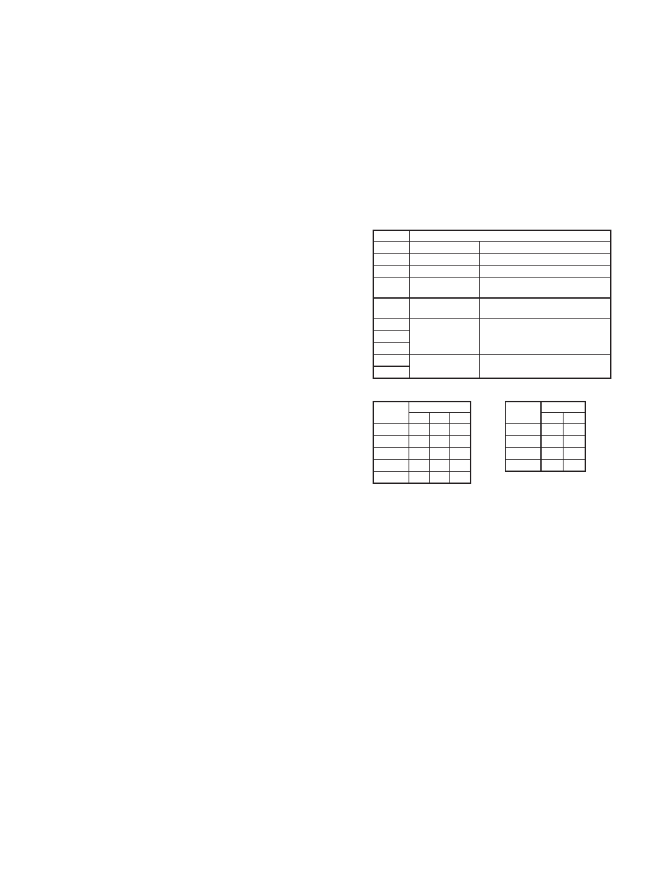
DIP SWITCH SETTING DESCRIPTIONS
SWITCH
DESCRIPTION
1
OUTPUT CAL Output Calibration
2
FIELD CAL Field Calibration
3
BASIC CAL Basic Calibration
4
ICE PT EN/DIS Ice Point Compensation -
Disabled (ON) / Enabled (OFF)
5
OPEN SEN DN/
UP
Open Sensor Detection -
Upscale (ON) / Downscale (OFF)
6
TC TYPE Thermocouple Type - 3 switch
combination setting
7
8
9
RANGE Sensor Range - 2 switch
combination setting
10
TC Type and Range switch settings (ON = 1 OFF = 0)
TC TYPE
DIP SWITCH
RANGE
DIP SWITCH
6
7
8
9
10
J
0
0
0
0
0
0
K
0
0
1
1
0
1
T
0
1
0
2
1
0
E
0
1
1
3
1
1
mV
1
1
1