Calibration procedures, 0 field calibration, Field calibration with a thermocouple calibrator – Red Lion ITMA User Manual
Page 4
4
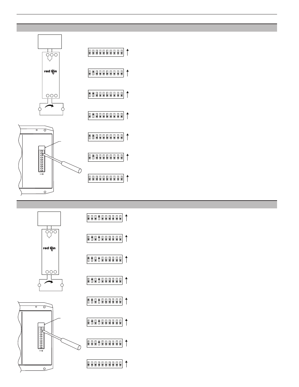
This calibration procedure can be used to assign the high and low input values if a
thermocouple calibrator is not available.
Note: To abort this calibration and reset to the previous settings, set the FIELD CAL
switch OFF prior to the final OFF setting of the OUTPUT CAL switch (Step 2.12) and
turn off power. Wait 5 seconds and then turn on power and the previous settings will
be loaded.
2.1 Connect the accurate Adjustable Millivolt Source to the TC input terminals.
2.2 Set the ICE PT EN/DIS switch (#4) ON to disable Ice Point Compensation.
2.3 Set the Type and Range for the thermocouple or mV used in your application
(DIP switches #6 through #10).(TC type “J”, Range 0 shown)
2.4 Set the FIELD CAL switch (#2) ON.[Current goes to 3.6 mA (nominal)]
2.5 Apply the input signal (mV equivalent for the thermocouple temperature) for the 4
mA output.
2.6 Set the OUTPUT CAL switch (#1) ON. [Current stays at 3.6 mA (nominal)]
2.7 Adjust the input signal up until the output equals 4 mA.
2.8 Set the OUTPUT CAL switch (#1) OFF. [Current increases to 22.3 mA (nominal)]
2.9 Apply the input signal (millivolt equivalent for the thermocouple temperature) for
the 20 mA output.
2.10 Set the OUTPUT CAL switch (#1) ON. [Current decreases to 20.5 mA (nominal)]
2.11 Adjust the input signal down until the output equals 20 mA.
2.12 Set the OUTPUT CAL switch (#1) OFF.
2.13 Set the FIELD CAL switch (#2) OFF.
2.14 Set the ICE PT EN/DIS switch (#4) OFF to enable Ice Point Compensation.
2.15 Disconnect millivolt source from the ITMA and connect the actual sensor to be used
in the application.
+
4 to 20 mA
Power Supply
12 to 42 VDC
±
M2068B
Current Display
Indicator
A
POWER/
OUTPUT
4
5
-
6
+
+
Thermocouple
Calibrator
TC
-
2
1
3
-
ITMA
Field Calibration Wiring
TEST
OUTPUT CAL
FIELD CAL
BASIC CAL
ICE PT EN/DIS
OPEN SEN DN/UP
TC TYPE
TC TYPE
TC TYPE
RANGE
RANGE
DIP SWITCH SETTINGS:
ON = 1
OFF = 0
M2069A
1
2
4
5
6
7
8
9
10
ON
Test
Pad
RED LION CONTROLS
YORK, PA.
MADE IN U.S.A.
MODEL ITMA
TEST
OUTPUT CAL
FIELD CAL
BASIC CAL
ICE PT EN/DIS
OPEN SEN DN/UP
TC TYPE
TC TYPE
TC TYPE
RANGE
RANGE
DIP SWITCH SETTINGS:
ON = 1
OFF = 0
M2069A
1
2
4
5
6
7
8
9
10
ON
Test
Pad
RED LION CONTROLS
YORK, PA.
MADE IN U.S.A.
MODEL ITMA
1
6
5
4
3
2
10
9
8
7
ON
1
6
5
4
3
2
10
9
8
7
ON
1
6
5
4
3
2
10
9
8
7
ON
1
6
5
4
3
2
10
9
8
7
ON
1
6
5
4
3
2
10
9
8
7
ON
1
6
5
4
3
2
10
9
8
7
ON
1
6
5
4
3
2
10
9
8
7
ON
Step 1.13
Step 1.3 & 1.4
Step 1.5
Step 1.7
Step 1.9
Step 1.11
Step 1.14
1.0 Field Calibration
CALIBRATION PROCEDURES
Field Calibration scales the 4 to 20 mA output to a temperature or mV input. This
procedure assigns an input value to 4 mA and an input value to 20 mA. The
microprocessor handles configuring the output so it is linear to the temperature or mV
input. The Field Calibration procedure is described below.
Note: Allow a 30 minute warm-up period before calibrating. The unit needs to have the
Field Calibration completed by the operator before normal operation. To abort this
calibration and reset to the previous settings, set the FIELD CAL switch OFF prior to
the final OFF setting of the OUTPUT CAL switch (Step 1.13) and turn off power. Wait
5 seconds and then turn on power and the previous settings will be loaded.
Field Calibration with a Thermocouple Calibrator
1.1 Enable the Ice Point Compensation on the Thermocouple Calibrator and set it to the
Thermocouple type being used in your application.
1.2 Connect the thermocouple wire as selected in step 1 to the TC input terminals of the
ITMA and the thermocouple calibrator.
1.3 Set the ICE PT EN/DIS switch (#4) OFF to enable Ice Point Compensation.
1.4 Set the Type and Range for the thermocouple or mV used in your application
(DIP switches #6 through #10). (TC type “J”, Range 0 shown)
1.5 Set the FIELD CAL switch (#2) ON. [Current goes to 3.6 mA (nominal)]
1.6 Apply the input signal for the 4 mA output.
1.7 Set the OUTPUT CAL switch (#1) ON. [Current stays at 3.6 mA (nominal)]
1.8 Adjust the input signal up until the output equals 4 mA.
1.9 Set the OUTPUT CAL switch (#1) OFF. [Current increases to 22.3 mA (nominal)]
1.10 Apply the input signal for the 20 mA output.
1.11 Set the OUTPUT CAL switch (#1) ON. [Current decreases to 20.5 mA (nominal)]
1.12 Adjust the input signal down until the output equals 20 mA.
1.13 Set the OUTPUT CAL switch (#1) OFF.
1.14 Set the FIELD CAL switch (#2) OFF.
1.15 Disconnect the thermocouple calibrator from the ITMA and connect the actual
sensor to be used in the application.
Power Supply
12 to 42 VDC
Current Display
4 to 20 mA
±
A
M2068B
POWER/
6
OUTPUT
+
4
5
-
Indicator
Adjustable
3
+
TC
-
1 2
Millivolt
Source
+ -
ITMA
1
6
5
4
3
2
10
9
8
7
ON
1
6
5
4
3
2
10
9
8
7
ON
1
6
5
4
3
2
10
9
8
7
ON
1
6
5
4
3
2
10
9
8
7
ON
1
6
5
4
3
2
10
9
8
7
ON
ON
1 2 3 4 5 6 7 8 9 10
4
1 2 3
ON
6
5
7 8 9 10
ON
1 2 3 4 5 6 7 8 9 10
Field Calibration Wiring
Step 2.2 & 2.3
Step 2.4
Step 2.6
Step 2.8
Step 2.10
Step 2.12
Step 2.13
Step 2.14
2.0 Field Calibration With an Accurate Adjustable Millivolt Source: (Alternate Method)