Function descriptions, Factory settings, Wiring connections – Red Lion ITMA User Manual
Page 2: Emc installation guidelines, Itma
2
5. TC BREAK DETECTION: Upscale to 22.5 mA (nominal) or Downscale to
3.6 mA (nominal) [selectable via DIP switch]
6. RESPONSE TIME: 400 msec (to within 99% of final value w/step input;
typically, response is limited to response time of probe.)
7. ENVIRONMENTAL CONDITIONS:
Operating Temperature Range: -25°C to 75°C (-13°F to 167°F)
Storage Temperature Range: -40°C to 85°C (-40°F to 185°F)
Operating and Storage Humidity: 85% max. (non-condensing) from -25°C
to 75°C.
Vibration to IEC 68-2-6: Operational 5-150 Hz, 2 g
Shock to IEC 68-2-27: Operational 30 g
Temperature Coefficient: ± 0.01% of input range per °C
Ice Point Compensation: ± 0.75°C for a 50°C change in temperature
Altitude: Up to 2000 meters.
8. DIELECTRIC WITHSTAND VOLTAGE: 1500 VAC for 1 minute, at 50
VAC working volts, from Input to Output
9. CERTIFICATIONS AND COMPLIANCES:
CE Approved
EN 61326-1 Immunity to Industrial Locations
Emission CISPR 11 Class A
IEC/EN 61010-1
Refer to the EMC Installation Guidelines section of this bulletin for
additional information.
10. MOUNTING: Universal mounting foot for attachment to standard DIN
style mounting rails, including top hat (T) profile rail according to EN50022
- 35
×
7.5 and 35
×
15, and G profile rail according to EN50035 - G32.
11. CONNECTION: Compression type terminal block
12. CONSTRUCTION: High impact black plastic case. Installation Category I,
Pollution Degree 2.
13. WEIGHT: 2.7 oz (76.54 g)
FUNCTION DESCRIPTIONS
Open Sensor Detection
The output can be set to go Upscale or Downscale for the detection of an
open sensor. The Upscale setting makes the output go to 22.5 mA (nominal).
The Downscale setting makes the output go to 3.5 mA (nominal). This setting
is always active, so changes in the setting are effective immediately.
Ice Point Compensation
The Ice Point Compensation for the thermocouple sensors can be enabled (DIP
Switch OFF) or disabled (DIP Switch ON). The mV sensor input is not affected
by this setting. Generally, the Ice Point Compensation is always enabled.
Calibration Malfunction
If the unit has scaling problems (current remains at 3.5 mA nominal), check
the voltage between the TC- Input (-) and TEST pad (+) [located next to the DIP
switches on the side of the unit]. For normal operation the voltage is -1.77 V
(nominal). If the voltage is +1.23 V(nominal), a problem occurred storing
information in the E
2
PROM. When this happens, perform a Basic Calibration
and then a Field Calibration. Turn off power for 5 seconds. Turn on power and
check the voltage between the TEST pad (+) and TC- Input (-). If the voltage is
still +1.23 V(nominal), contact the factory.
FACTORY SETTINGS
The unit is shipped from the factory calibrated for a 4 to 20 mA output using
a type J thermocouple in range 3. The ITMA should be Field calibrated by the
operator for the application environment it will be used in. If the unit is not
recalibrated by the operator, the following table lists the temperature ranges for
the given thermocouple types.
TYPE
RANGE
TEMPERATURE RANGE
J
3
-50°C to 500°C
K
3
-85°C to 790°C
T
3
-195°C to 162°C
E
3
3°C to 602°C
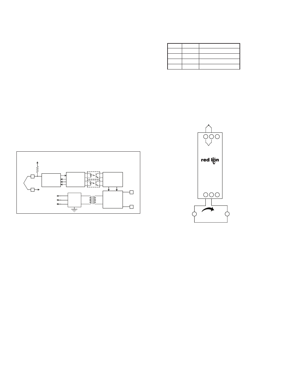
WIRING CONNECTIONS
All conductors should meet voltage and current ratings for each terminal.
Also, cabling should conform to appropriate standards of good installation,
local codes and regulations. It is recommended that power supplied to the unit
be protected by a fuse or circuit breaker. When wiring the unit, use the numbers
on the label to identify the position number with the proper function. Strip the
wire, leaving approximately 1/4" (6 mm) of bare wire exposed (stranded wire
should be tinned with solder). Insert the wire into the terminal, and tighten the
screw until the wire is clamped tightly.
EMC INSTALLATION GUIDELINES
Although Red Lion Controls Products are designed with a high degree of
immunity to Electromagnetic Interference (EMI), proper installation and wiring
methods must be followed to ensure compatibility in each application. The type
of the electrical noise, source or coupling method into a unit may be different
for various installations. Cable length, routing, and shield termination are very
important and can mean the difference between a successful or troublesome
installation. Listed are some EMI guidelines for a successful installation in an
industrial environment.
1. A unit should be mounted in a metal enclosure, which is properly connected
to protective earth.
2. Use shielded cables for all Signal and Control inputs. The shield connection
should be made as short as possible. The connection point for the shield
depends somewhat upon the application. Listed below are the recommended
methods of connecting the shield, in order of their effectiveness.
a. Connect the shield to earth ground (protective earth) at one end where the
unit is mounted.
b. Connect the shield to earth ground at both ends of the cable, usually when
the noise source frequency is over 1 MHz.
3. Never run Signal or Control cables in the same conduit or raceway with AC
power lines, conductors, feeding motors, solenoids, SCR controls, and
heaters, etc. The cables should be run through metal conduit that is properly
grounded. This is especially useful in applications where cable runs are long
and portable two-way radios are used in close proximity or if the installation
is near a commercial radio transmitter. Also, Signal or Control cables within
an enclosure should be routed as far away as possible from contactors,
control relays, transformers, and other noisy components.
4. Long cable runs are more susceptible to EMI pickup than short cable runs.
Current Display
Indicator or
Power Supply
12 to 42 VDC
4 to 20 mA
±
A
OUTPUT
POWER/
M2068B
+
4
5
-
6
TC
TC
+
1
-
2
3
Monitoring
Instrument
ITMA
LOOP
POWER
CIRCUITRY
4
5
CIRCUITRY
CONTROL
PWM
POWER
SUPPLY
4V
3V
1.7V
CIRCUITRY
PROCESS
CONVERTER
A/D
2
1
1.7V
3V
22M
TC
+
-
POWER/
OUTPUT
BLOCK DIAGRAM