Recalibrating factory stored values, Troubleshooting, Installation – Red Lion IAMA User Manual
Page 7
7
The following list outlines conditions that are unique to factory recalibration:
1. Unlike the field scaling procedures, there are no software under and over
range indications while performing a factory recalibration. Therefore, care
must be taken to insure the selected range extents are not exceeded. The
minimum scale and full scale calibration values must be set to the extents
of the range being calibrated.
For example: If the Input Range DIP switches are set for the 4-20 mA
range, minimum scale must be set at 4 mA, and full scale must be set at
20 mA.
2. At least one input calibration must be completed before calibrating any
output range. When calibrating the input voltage range, it is recommended
that a range above 1 V be used to provide better accuracy.
3. If multiple input or output ranges are to be calibrated, DO NOT REMOVE
POWER TO CHANGE THE RANGE. Place the appropriate Field/Fact.
DIP switch; S1-1 for outputs, and S1-2 for inputs to the down position, and
set the remaining DIP switches for the range to be calibrated. Note: Be sure
to change the terminal wiring to match the Input or Output range DIP
switch settings before performing the calibration procedure. Set calibration
source to 0 V or 0 mA before changing wiring.
INPUT RECALIBRATION
1. To enter the factory calibration mode, set switches S1-1 and S1-2 down, S1-3
through S1-5 up, and S1-6 through S1-10 down.
2. Connect a signal source to the correct input terminals based on the maximum
signal input to be calibrated. If an output range will be calibrated after the
input range is calibrated, connect a voltage or current meter to the appropriate
output terminals at this time.
3. Apply power to the IAMA. After the version number indication, the green
LED will flash rapidly for 2 seconds indicating the factory calibration mode
has been entered. Allow the IAMA to warm up for 5 minutes minimum and
follow the manufacturer’s warm up procedure for the calibration source.
4. Set the Input Range DIP switches to the desired input range according to
Table 3.
5. Complete Steps 2.6 through 2.10 of Input Scaling Using Field Configuration.
Note: There will be no over or under range indication of the LED’s during
this procedure, so use care not to exceed the range extents.
6. If an output is to be calibrated, continue from #2 of Output Recalibration
below. If no further input or output calibration is to be completed, return
S1-1 and S1-2 to the down position and remove power from the IAMA.
Apply power and check for accurate operation of the newly calibrated range
or ranges.
OUTPUT RECALIBRATION
1. Complete 1 through 5 of the input recalibration procedure for at least
one range.
2. For current output, set 20 mA/1 mA switch (S2) to desired full scale output.
(20 mA - on; 1 mA - off)
3. Set Output Field/Fact. switch (S1 switch 1) to the off position.
4. Set the Output Range DIP switches to the desired output range according to
Table 2.
5. Complete Steps 4.10 through 4.14 of Output Scaling Using Field
Configuration. Note: There will be no over or under range indication of the
LED’s during this procedure, so use care not to exceed the range extents.
6. If no further calibration is to be completed, return S1-1 and S1-2 to the down
position and remove power from the IAMA. Apply power and check for
accurate operation of the newly calibrated range or ranges.
RECALIBRATING FACTORY STORED VALUES
WARNING: Read the complete procedure at least
once before attempting to recalibrate the factory
values. This procedure should only be performed
due to factory checksum error or unacceptable
error. This procedure should be performed by
qualified technicians using accurate calibration
equipment.
TROUBLESHOOTING
For further technical assistance, contact technical support at the appropriate company numbers listed.
INSTALLATION
The unit is equipped with a universal mounting foot for attachment to standard DIN style mounting rails, including G profile rail
according to EN50035 - G32 , and top hat (T) profile rail according to EN50022 - 35 x 7.5 and 35 x 15. The unit should be installed in a
location that does not exceed the maximum operating temperature and provides good air circulation. Placing the unit near devices that
generate excessive heat should be avoided.
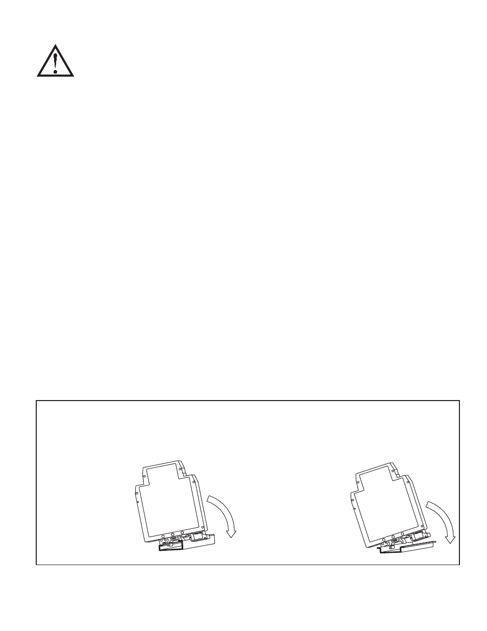
G Rail Installation
To install the IAMA on a “G”
style DIN rail, angle the module
so that the upper groove of the
“foot” catches under the lip of the
top rail. Push the module toward
the rail until it snaps into place.
To remove a module from the
rail, push up on the bottom of the
module while pulling out and
away from the rail.
T Rail Installation
To install the IAMA on a “T”
style rail, angle the module so
that the top groove of the “foot”
is located over the lip of the top
rail. Push the module toward the
rail until it snaps into place. To
remove a module from the rail,
insert a screwdriver into the slot
on the bottom of the “foot”, and
pry upwards on the module until
it releases from the rail.