Getting started, Field or factory mode selection, Emc installation guidelines – Red Lion IAMA User Manual
Page 3: Wiring connections
3
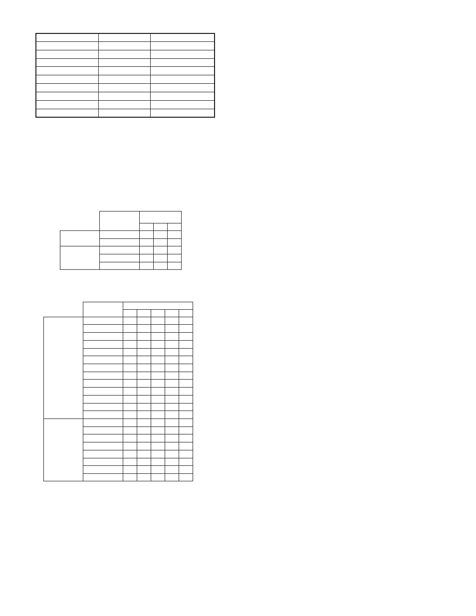
TABLE 1, LED INDICATIONS
GETTING STARTED
One method for the Input (1 or 2 below) should be configured, and one
method for the Output (3 or 4 below) should be configured.
1. FACTORY preprogrammed settings for the Input, see Section 1.0
2. FIELD scaling method for the Input, see Section 2.0
3. FACTORY preprogrammed setting for the Output, see Section 3.0
4. FIELD scaling method for the Output, see Section 4.0
Note: The ranges should only be changed while power is removed from the IAMA.
TABLE 2, OUTPUT RANGE SETTINGS
TABLE 3, INPUT RANGE SETTINGS
FIELD OR FACTORY MODE SELECTION
SELECTING FIELD MODE (2 Methods):
1. Scale the input or output according to SCALING PROCEDURE 2.0 or 4.0
2. Before applying power, set the input or output (or both) field/factory switch
to the up (field) position. Field calibration values will be restored upon
power-up. If the IAMA has not been previously field calibrated, the E
2
PROM
will contain the factory calibration values which will be restored.
SELECTING FACTORY MODE (2 Methods):
1. Before applying power to the IAMA set the input or output (or both) field/
factory switch to the down (factory) position. Factory calibration values will
be restored upon power-up.
2. While power is applied to the IAMA and it is operating in the field input and/
or output mode, set the desired field/factory switch(s) to the down (factory)
position. The factory calibration values will be restored.
EMC INSTALLATION GUIDELINES
Although Red Lion Controls Products are designed with a high degree of
immunity to Electromagnetic Interference (EMI), proper installation and wiring
methods must be followed to ensure compatibility in each application. The type
of the electrical noise, source or coupling method into a unit may be different
for various installations. Cable length, routing, and shield termination are very
important and can mean the difference between a successful or troublesome
installation. Listed are some EMI guidelines for a successful installation in an
industrial environment.
1. A unit should be mounted in a metal enclosure, which is properly connected
to protective earth.
2. Use shielded cables for all Signal and Control inputs. The shield connection
should be made as short as possible. The connection point for the shield
depends somewhat upon the application. Listed below are the recommended
methods of connecting the shield, in order of their effectiveness.
a. Connect the shield to earth ground (protective earth) at one end where the
unit is mounted.
b. Connect the shield to earth ground at both ends of the cable, usually when
the noise source frequency is over 1 MHz.
3. Never run Signal or Control cables in the same conduit or raceway with AC
power lines, conductors, feeding motors, solenoids, SCR controls, and
heaters, etc. The cables should be run through metal conduit that is properly
grounded. This is especially useful in applications where cable runs are long
and portable two-way radios are used in close proximity or if the installation
is near a commercial radio transmitter. Also, Signal or Control cables within
an enclosure should be routed as far away as possible from contactors,
control relays, transformers, and other noisy components.
4. Long cable runs are more susceptible to EMI pickup than short cable runs.
5. In extremely high EMI environments, the use of external EMI suppression
devices such as Ferrite Suppression Cores for signal and control cables is
effective. The following EMI suppression devices (or equivalent) are
recommended:
Fair-Rite part number 0443167251 (RLC part number FCOR0000)
Line Filters for input power cables:
Schaffner # FN2010-1/07 (Red Lion Controls # LFIL0000)
6. To protect relay contacts that control inductive loads and to minimize radiated
and conducted noise (EMI), some type of contact protection network is
normally installed across the load, the contacts or both. The most effective
location is across the load.
a. Using a snubber, which is a resistor-capacitor (RC) network or metal oxide
varistor (MOV) across an AC inductive load is very effective at reducing
EMI and increasing relay contact life.
b. If a DC inductive load (such as a DC relay coil) is controlled by a transistor
switch, care must be taken not to exceed the breakdown voltage of the
transistor when the load is switched. One of the most effective ways is to
place a diode across the inductive load. Most RLC products with solid
state outputs have internal zener diode protection. However external diode
protection at the load is always a good design practice to limit EMI.
Although the use of a snubber or varistor could be used.
RLC part numbers: Snubber: SNUB0000
Varistor: ILS11500 or ILS23000
7. Care should be taken when connecting input and output devices to the
instrument. When a separate input and output common is provided, they
should not be mixed. Therefore a sensor common should NOT be connected
to an output common. This would cause EMI on the sensitive input common,
which could affect the instrument’s operation.
Visit RLC’s web site at http://www.redlion.net/Support/InstallationConsiderations.
html for more information on EMI guidelines, Safety and CE issues as they
relate to Red Lion Controls products.
WIRING CONNECTIONS
All conductors should meet voltage and current ratings for each terminal.
Also cabling should conform to appropriate standards of good installation, local
codes and regulations. It is recommended that power supplied to the unit be
protected by a fuse or circuit breaker. When wiring the unit, use the numbers on
the label to identify the position number with the proper function. Strip the wire,
leaving approximately 1/4" (6 mm) of bare wire exposed. Insert the wire into
the terminal, and tighten the screw until the wire is clamped tightly.
RANGE DIP
SWITCHES
3
4
5
OUTPUT
RANGE
0 - 5 V
0
0
0
VOLTAGE
OUTPUTS
0 - 10 V
0
0
1
0 - 1 mA
0
1
0
4 - 20 mA
0
1
1
CURRENT
OUTPUTS
0 - 20 mA
1
0
0
Note: DIP switch settings 0 = OFF 1 = ON
Note: DIP switch settings 0 = OFF 1 = ON
RANGE
RANGE DIP SWITCHES
6
7
8
9
10
INPUT
VOLTAGE
0 - 20 mV
0
0
0
0
0
0 - 50 mV
0
0
0
0
1
0 - 100 mV
0
0
0
1
0
0 - 200 mV
0
0
0
1
1
0 - 500 mV
0
0
1
0
0
0 - 1 V
0
0
1
0
1
0 - 2 V
0
0
1
1
0
1 - 5 V
0
0
1
1
1
0 - 5 V
0
1
0
0
0
0 - 10 V
0
1
0
0
1
0 - 20 V
0
1
0
1
0
0 - 50 V
0
1
0
1
1
0 - 100 V
0
1
1
0
0
0 - 1 mA
0
1
1
0
1
0 - 2 mA
0
1
1
1
0
0 - 5 mA
0
1
1
1
1
0 - 10 mA
1
0
0
0
0
4 - 20 mA
1
0
0
0
1
0 - 20 mA
1
0
0
1
0
0 - 50 mA
1
0
0
1
1
INPUT
CURRENT
0 - 100 mA
1
0
1
0
0
CONDITION
GREEN LED
RED LED
Normal Operation
On
Off
Scaling Mode
Alternate with Red Alternate with Green
Under Range
Off
Slow Flash (0.8 sec rate)
Over Range
Off
Fast Flash (0.4 sec rate)
Invalid Range
Off
On
Illegal Range Change
Off
On
Factory Checksum
Off
On, short off
Field Checksum
On, short off
Off
User Factory Calibration Fast Flash for 2 sec Off