0 output scaling using field configuration – Red Lion IAMA User Manual
Page 6
6
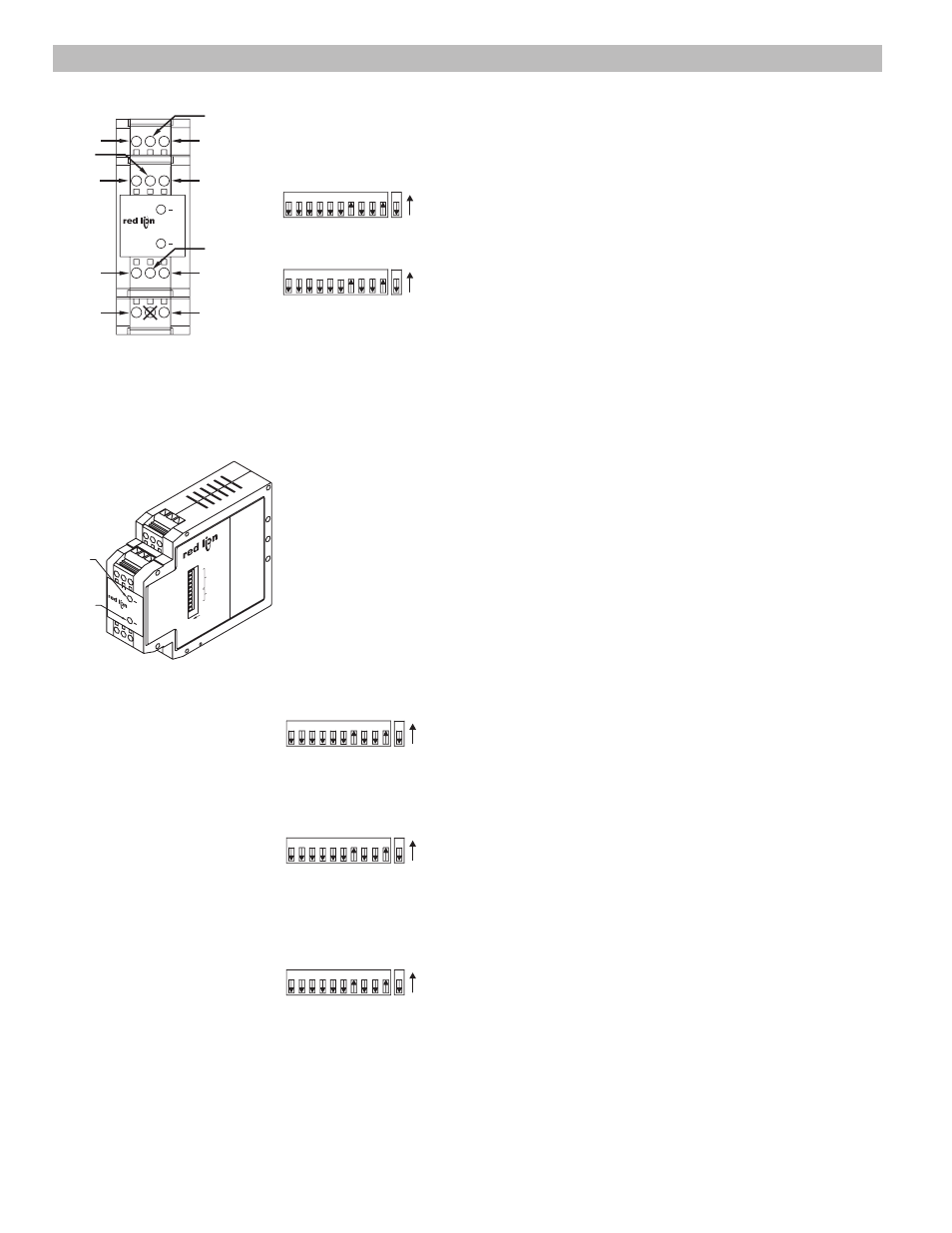
4.1 Remove power.
4.2 For voltage output scaling, go to Step 4.4.
For current output scaling, continue at Step 4.3.
4.3 Set 20 mA/1 mA switch (S2) to desired full scale output.
(20 mA - on; 1 mA - off)
4.4 Set Output Field/Fact. switch (S1 switch 1) to the off position.
4.5 Set Output Range switches (S1 switches 3, 4, and 5) to the desired Output Range
(See Table 2). Select the lowest possible range that will support the desired full
scale output. Example: if the desired span is 1 V to 4 V, the best range selection is
0 to 5 V. (0 to 5 VDC range shown)
4.6 Connect volt or current meter to appropriate IAMA output terminals.
Terminal 6: + Voltage
Terminal 5: - Voltage
Terminal 4: + Current
Terminal 1: - Current
4.7 An input signal is required to complete output scaling. If previous scaled input is
used (completed in Step 2.0), Input Field/Fact. switch (S1 switch 2) and Input
Range switches (S1 switches 6 through 10) must remain in the same positions. If
another signal source is used, set Input Field/Fact. switch (S1 switch 2) to off
position and Input Range switches (S1 switches 6 through 10) to the desired input
range (See Table 3).
4.8 Connect input signal source to the correct input terminals based on the maximum
signal input.
Terminal 7: max. signal input 1 VDC
Terminal 8: max. signal input 10 VDC
Terminal 9: max. signal input 100 VDC
Terminal 10: max. signal input 100 mA
Terminal 12: signal common
4.9 Apply power to the IAMA and allow a warm up period of five minutes.
4.10 Set Output Field/Fact. switch (S1 switch 1) to the on position.
The Red and Green LEDs will alternately blink.
If Red LED blinks slowly, increase signal until Red and Green LEDs alternately
blink.
4.11 Adjust the input signal until the desired * minimum output level is displayed on
the volt or current meter.
The Red and Green LEDs will alternately blink.
4.12 Set Output Field/Fact. switch (S1 switch 1) to the off position.
The Red and Green LEDs alternately blink.
If the signal is equal to or below the minimum limit of the selected range, the Red
LED blinks slowly and the Green LED turns off. Removing power aborts scaling.
Start over at Step 4.1.
4.13 Adjust the input signal until the desired * maximum output level is displayed on
the volt or current meter.
4.14 Set Output Field/Fact. switch (S1 switch 1) to the on position.
Red LED extinguishes and Green LED becomes solid. Your scaled values are now
saved and will be recalled if the Output Field/Fact. switch (S1 switch 1) is in
the on position when power is applied.
4.15 Output scaling is complete.
* If the minimum output is higher than the maximum output the module reverses
its output behaviour accordingly.
4.0 OUTPUT SCALING USING FIELD CONFIGURATION
ON
2
1
3
5
4
6
S1
8
7
9 10 1
S2
Step 4.4
ON
2
1
3
5
4
6
S1
8
7
9 10 1
S2
Step 4.5
ON
2
1
3
5
4
6
S1
8
7
9 10 1
S2
Step 4.10
ON
2
1
3
5
4
6
S1
8
7
9 10 1
S2
Step 4.12
ON
2
1
3
5
4
6
S1
8
7
9 10 1
S2
Step 4.14
OUT-
OUT+
10V
COMM
INPUT
I
IN
OUT-
OUT+
1V
V
V
I
I
S
MC2290D
A
U
T
T
S
100V
1 2 3
6
5
4
7 8 9
12
10
~-
DC+
~-
(AC)
DC-
(AC)
IAMA
OUTPUT RANG
E
INPUT RANGE
20mA/1mA OUTPUT
IN FIELD/FACT
.
OUT FIELD/FACT
.
7
ON
1
6
5
4
3
2
10
9
8
IAMA
S
T
A
T
U
S
GREEN
LED
RED
LED