Module isolation, Overview, Inputs – Red Lion IAMA User Manual
Page 2: Outputs, Zero and span, Illegal range selections and changes, Checksum errors
2
13. ACCURACY (INCLUDING LINEARITY): Factory: ±0.1% of span
max. for all ranges except 1 mA, 2 mA, and 20 mV. These ranges are
accurate to ±0.2% of span max. All ranges can be field calibrated to 0.1%
of span max.
14. RESOLUTION: 0.01% full scale input, 0.01% full scale output
15. ENVIRONMENTAL CONDITIONS:
Operating Temperature Range: -20 to +65 °C
Storage Temperature Range: -40 to +85 °C
Operating and Storage Humidity: 85% max. relative humidity (non-
condensing) from -20 to +65 °C
Temperature Coefficient: ± 0.01%/°C (100 PPM/°C) max.
Vibration to IEC 68-2-6: Operational 5 to 150 Hz, 2 g.
Shock to IEC 68-2-27: Operational 30 g
Altitude: Up to 2000 meters
16. CERTIFICATIONS AND COMPLIANCES:
CE Approved
EN 61326-1 Immunity to Industrial Locations
Emission CISPR 11 Class A
IEC/EN 61010-1
UL Recognized Component: File #E179259
Refer to EMC Installation Guidelines section of this bulletin for additional
information.
17. CONSTRUCTION: Case body is black high impact plastic
18. CONNECTIONS: 14 AWG max
19. MOUNTING: Standard DIN top hat (T) profile rail according to EN50022
- 35x7.5 and 35 x 15 and G profile rail according to EN50035-G32.
20. WEIGHT: 4.5 oz. (127.57 g)
MODULE ISOLATION
IAMA modules feature “3-Way” Signal Isolation. The 3-Way isolation is a
combination of optical and transformer isolation. The optical isolation provides
common mode voltage (CMV) isolation up to 1.5 kV between the sensor input
and the process signal output. The IAMA’s power is isolated from the sensor
signal input and the process signal output by a DC/DC transformer isolation
circuit.
OVERVIEW
The IAMA3535 continuously monitors a voltage or current input and
provides a linearly proportional voltage or current output, while the IAMA6262
transmits the scaled square root of the input signal. This allows the IAMA6262
to provide a signal that is linear to flow rate in applications utilizing a
differential pressure transducer. Both units have two modes of operation known
as Factory and Field modes. Factory mode is used when the default input and
output ranges are suitable. Field mode can be independently selected for both
the input and output, and allows the user to custom calibrate, or scale the signal.
If Factory mode is selected, the IAMAs use factory presets for the selected input
or output range. If Field mode is selected, the IAMAs can be custom scaled
within a selected input or output range. Field mode also allows the IAMA to
reverse its output in relation to its input.
The units are factory precalibrated for minimum and full scale for all input
and output ranges. The factory calibration values are permanently stored in
E
2
PROM and should not be changed in the field, unless unacceptable error or a
factory checksum error occurs. See Factory Recalibration for details. Field
scaling is achieved by applying minimum and full scale values from a
calibration source and storing the values by a single DIP switch transition. Field
scaling is available for all input and output ranges and the values are
permanently stored in E
2
PROM until reprogramming occurs.
After field scaling, the IAMAs can be changed between Factory and Field
modes for a particular range, which restores the respective setting. The Factory
and Field E
2
PROM locations contain the same calibration values when the
IAMA is received from the factory. Therefore, until the IAMA is field scaled,
factory and field modes perform identically. See SCALING PROCEDURE for
detailed instructions on field programming the IAMA.
The units can be scaled to any minimum scale and full scale values within the
extent of the selected range. The closer together the minimum and full scale
values are to each other, the less accurate the signal will be. For example, if the
0 to 1 V input range is selected, and the unit is scaled for 0 to 0.5 V, the signal
has the same resolution as the 0 to 1 V range. Since this resolution will be two
times the percentage of span for 0.5 V, more accuracy can be achieved by using
the 0 to 0.5 V range.
The input may exceed the full scale value for the selected range by 10% of
span, but the IAMA will not update the output beyond 10% over range.
The red and green LED’s indicate the status of the modules during scaling and
normal operation. Table 1, LED Indications, details the LED indications for
various unit conditions.
The IAMA – Signal Conditioning Module Series is designed for use in
industrial environments. Suppressor diodes protect both input and output
circuits from wiring errors and transient high voltage conditions.
INPUTS
The IAMAs accept a full range of process signal inputs and isolate and
convert these signals to common industrial control signals. The input signal
combinations are configured by making specific DIP switch selections on the 10
position DIP switch.
OUTPUTS
As with the input choices, the process signal output of the modules is DIP
switch selectable. A 1 position DIP switch is used to select between the 1 mA/20
mA output ranges. The maximum output current signal is 22 mA with ≤600 Ω
output resistance and the maximum output voltage signal is 11 V with ≥1 KΩ
output resistance.
ZERO AND SPAN
The input zero and span are set by first applying the minimum value then
transitioning S1-2 to store that value. Next, the full scale value is applied and the
DIP switch transition stores the value. The output scaling is performed in a
similar manner but the output is driven to the desired minimum and full scale
values by the calibration source applied to the input. S1-1 is used to store the
minimum and full scale output values.
The span is defined by: span = (full scale - minimum scale).
ILLEGAL RANGE SELECTIONS AND CHANGES
The ranges should only be selected before power is applied. If an invalid input
or output range is selected when power is applied the output is set to approximately
0 VDC and the red LED indicates the error according to Table 1. Power must be
removed and valid ranges selected for the IAMA to operate properly.
If S1 switches 3 through 10 are changed while the IAMA is operating, the red
LED indicates a range change according to Table 1, LED Indications and the
output goes to the previously stored range minimum scale value. Normal
operation will be resumed if the switches are placed back in the previous
positions or power is removed and restored.
CHECKSUM ERRORS
A checksum is performed every time power is applied to the IAMA. If a
checksum error occurs, the LEDs will indicate where the error occurred
according to Table 1, LED Indications. Operation with a checksum error is not
recommended but can be done in critical situations. If an error occurs,
re-calibration of the field or factory ranges to be used must be performed.
If a field checksum error occurs, the IAMA will operate only in factory mode.
If a factory checksum occurs, the IAMA will operate only in a previously
calibrated field mode. Do not perform a field scaling until the factory checksum is
cleared. Since a checksum error is a high priority LED indication, the LEDs will
indicate the error until it is cleared. This will exclude other LED information.
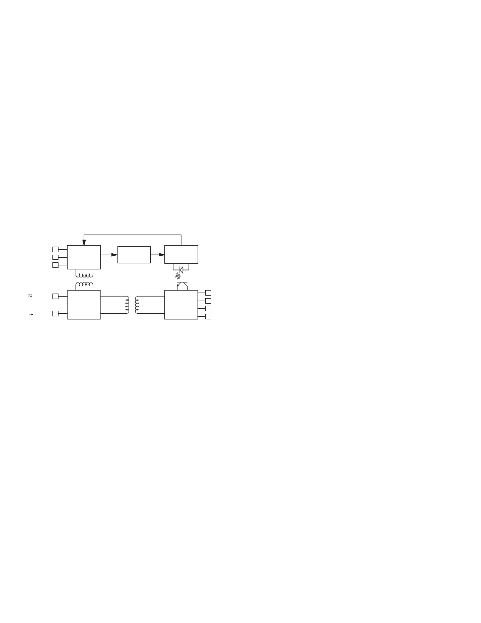
*
10
12
VARIABLE
GAIN
AMP
V/F
CONVERTER
PROCESS
CIRCUITY
6
5
1
4
PWM
CIRCUITRY
V
V
I
I
3
2
POWER
SUPPLY
V
I
INPUT
COMMON
IN
IN
OUT+
OUT-
OUT+
OUT-
DC- (AC)
DC+ (AC)
BLOCK DIAGRAM
*
Terminal number is dependent on max. input voltage.