Output features, Auto-tune, Profile programming – Red Lion TSC User Manual
Page 5: Controller programming, Hidden functions mode, Output variations without rs485 option, Output variations with rs485 option, Unprotected parameter mode, Protected parameter mode
5
OUTPUT FEATURES
Programmable output power limits provide protection for processes where
too much power can cause damage. Automatic sensor probe break detection, for
fail-safe operation, causes the controller to default to a programmed output
power (upscale or downscale burnout). With adjustable time proportioning-
cycle time and programmable D.C. Linear output, the controller can satisfy a
wide variety of output requirements.
During execution of a profile, two independent, timed event outputs are
available to control or signal other equipment. The event outputs use the alarm
channels.
The RS485 Communication option allows the user to access various
controller parameters such as the setpoint, % output power, % proportional
band, etc. The controller may be setup to transmit various parameters at a
programmable automatic print rate.
AUTO-TUNE
The model TSC has an auto-tune feature which, on demand, automatically
determines the PID control parameters for a particular thermal process. After
completion of auto-tune, the PID parameters are automatically optimized for
that process and loaded into nonvolatile memory. The operator may view and
modify the parameters as desired.
Auto-tune may be invoked at start-up, while ramping, or at setpoint,
depending on the process requirements. A programmable auto-tune damping
factor produces various levels of process control and response characteristics.
PROFILE PROGRAMMING
Profiles are programmed independently of each other and are separate from
the configuration of other controller parameters. Each profile has parameters for
error band (profile conformity), linking, auto-start and program repeat cycles.
Profiles may be altered during execution, so changes take effect as the
programmed profile advances.
CONTROLLER PROGRAMMING
The model TSC has been designed to reduce the operator interaction with the
controller while still maintaining a high degree of control accuracy and user
flexibility. Front panel program disable allows all of the controller’s set-ups to be
locked-out from further operator intervention after the initial parameter set-up.
The programming of the controller is divided into four sections:
Hidden Mode
Protected Mode
Unprotected Mode
Configuration Mode
These four programming modes allow the controller to adapt to any required
user-interface level.
UNPROTECTED PARAMETER MODE
The unprotected mode is accessible when program disable is inactive or when
the proper access code number from the protected mode is entered. Only from
this mode can the configuration modes be accessed.
“SP”
- Enter setpoint
*
“OPOF”
- Enter %output power offset
*
“OP”
- Enter output power
*
“ProP”
- Enter proportional band
“Intt”
- Enter integral time
*
“dErt”
- Enter derivative time
*
“AL-1”
- Enter value for alarm #1
*
“AL-2”
- Enter value for alarm #2
*
“CNFP”
- Select basic configuration module
“End”
- Return to normal display mode
PROTECTED PARAMETER MODE *
The protected mode is accessible when program disable is active, also this
mode prevents access to the configuration modes without the proper access code
number. Only the parameters that are selected in the configuration 3 parameter
lock-outs section can be accessed.
“ProP”
- Enter proportional band
“Intt”
- Enter integral time
“dErt”
- Enter derivative time
“AL-1”
- Enter value for alarm #1
“AL-2”
- Enter value for alarm #2
“CodE”
- Enter access value to unprotected mode
“End”
- Return to normal display mode
HIDDEN FUNCTIONS MODE
*
The hidden mode is accessible from the normal operating mode by holding
the PAR button for 3 seconds. The five functions in this mode may be locked-out
individually in configuration 3 parameter lock-outs section.
“ CP”
- Load control point x
“Prun”
- Control ramp/hold profile state
“trnF”
- Transfer between automatic (PID) control
and Manual control
“tUNE”
- Invoke/Cancel PID auto-tune
“ALrS”
- Reset latched alarms
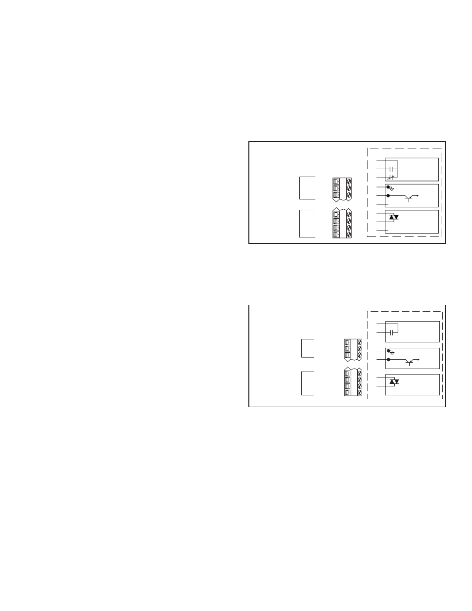
OUTPUT VARIATIONS WITHOUT RS485 OPTION
The Dual Alarm or the Cooling with Alarm output, without the RS485 option,
has independent outputs. Therefore, the cooling output and/or alarm output(s)
can be installed with any combination of output modules.
OUTPUT VARIATIONS WITH RS485 OPTION
The Dual Alarm or the Cooling with Alarm output, with RS485 option, does
not have independent outputs. In this case, the cooling output and/or alarm
output(s) must have the same type of output modules installed since they share
the common terminal.
*
These parameters may not appear due to option configuration or other
programming
3
2
1
AL2/OP2-C
AL2/OP2-B
AL2/OP2-A
OPTION
COOLING
OUTPUT 2
ALARM 2 OR
16
15
14
13
AL1-C
AL1-B
AL1-A
N/C
OPTION
ALARM 1
DUAL ALARM OR
COOLING W/ALARM OPTION
WITHOUT RS-485 OPTION
ALARM 1 AND ALARM 2
3
2
1
AL1-B
AL2/OP2-B
AL/OP2 COMM.-A
OPTION
COOLING
ALARM 1 WITH
OR
16
15
14
13
RS-485 COMM.
TX EN.
TX/RX(-)
TX/RX(+)
OPTION
RS-485
DUAL ALARM OR
COOLING W/ALARM OPTION
WITH RS-485 OPTION
C
B
A
DO NOT CONNECT
TRIAC
(ISOLATED)
1A @ 240VAC
LOGIC/SSR DRIVE
DO NOT CONNECT
+
-
(RESISTIVE LOAD)
5A @ 240VAC
RELAY
A
B
C
C
B
A
OUTPUT MODULES
+12VDC
NOT
ISOLATED
OUTPUT MODULES
A
B
B
A
RELAY
5A @ 240VAC
(RESISTIVE LOAD)
1A @ 240VAC
(ISOLATED)
TRIAC
A
B
ISOLATED
NOT
+12VDC
-
+
LOGIC/SSR DRIVE