1 module 1 - s, Ignal, Nput – Red Lion LDSG User Manual
Page 6: Arameters
66
ALTERNATING SELECTION DISPLAY
In the module description sections which follow, the dual display with arrows
appears for each programming parameter. This is used to illustrate the display
alternating between the parameter (top display) and the parameter's Factory
Setting (bottom display). In most cases, selections or value ranges for the
parameter will be listed on the right.
STEP BY STEP PROGRAMMING INSTRUCTIONS:
PROGRAMMING MODE ENTRY (PAR KEY)
The Programming Mode is entered by pressing the
PAR
key. If this mode is
not accessible, then meter programming is locked by either a security code or a
hardware lock. (See Modules 2 and 3 for programming lock-out details.)
MODULE ENTRY (ARROW & PAR KEYS)
Upon entering the Programming Mode, the display alternates between
and the present module (initially ). The arrow keys (
F1
and
F2
) are used
to select the desired module, which is then entered by pressing the
PAR
key.
PARAMETER (MODULE) MENU (PAR KEY)
Each module has a separate parameter menu. These menus are shown at the
start of each module description section which follows. The
PAR
key is pressed
to advance to a particular parameter to be changed, without changing the
programming of preceding parameters. After completing a module, the display
will return to . From this point, programming may continue by selecting
and entering additional modules. (See
MODULE ENTRY above.)
PARAMETER SELECTION ENTRY (ARROW & PAR KEYS)
For each parameter, the display alternates between the parameter and the
present selection or value for that parameter. For parameters which have a list
of selections, the arrow keys (
F1
and
F2
) are used to sequence through the
list until the desired selection is displayed. Pressing the
PAR
key stores and
activates the displayed selection, and also advances the meter to the next
parameter.
NUMERICAL VALUE ENTRY (ARROW, RST & PAR KEYS)
For parameters which require a numerical value entry, the arrow keys can be
used to increment or decrement the display to the desired value. When an arrow
key is pressed and held, the display automatically scrolls up or scrolls down.
The longer the key is held, the faster the display scrolls.
The
RST
key can be used in combination with the arrow keys to enter large
numerical values. When the
RST
key is pressed along with an arrow key, the
display scrolls by 1000’s. Pressing the
PAR
key stores and activates the
displayed value, and also advances the meter to the next parameter.
PROGRAMMING MODE EXIT (DSP KEY or PAR KEY at
)
The Programming Mode is exited by pressing the
DSP
key (from anywhere
in the Programming Mode) or the
PAR
key (with displayed). This will
commit any stored parameter changes to memory and return the meter to the
Display Mode. If a parameter was just changed, the
PAR
key should be pressed
to store the change before pressing the
DSP
key. (If power loss occurs before
returning to the Display Mode, verify recent parameter changes.)
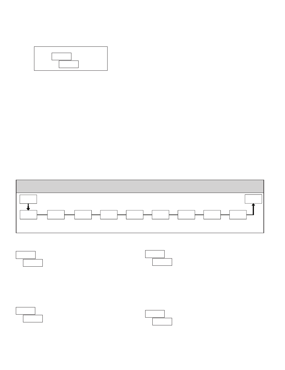
5.1 Module 1 - s
Ignal
I
nput
p
araMeters
(
)
1-INP
Display
Decimal Point
dECPt
Input
Range
rAN6E
Display
Rounding
round
Scaling
Style
StYLE
FILtr
Filter
Setting
bANd
Filter
Band
Scaling
Points
PtS
Display x
Value
dSP
Input x
Value
INP
x
x
PAR
Pro
PARAMETER MENU
INPUT RANGE
Select the input range that corresponds to the external signal. This selection
should be high enough to avoid input signal overload but low enough for the
desired input resolution. This selection and the position of the Input Range
Jumper must match.
RANGE
RESOLUTION
SELECTION
±24 mV
±240 mV
DISPLAY DECIMAL POINT
Select the decimal point location for the Input,
MAX and MIN displays. (The
TOT display decimal point is a separate parameter.) This selection also affects
,
and
parameters and setpoint values.
DISPLAY ROUNDING*
Rounding selections other than one, cause the Input Display to ‘round’ to the
nearest rounding increment selected (ie. rounding of ‘5’ causes 122 to round to
120 and 123 to round to 125). Rounding starts at the least significant digit of
the Input Display. Remaining parameter entries (scaling point values, setpoint
values, etc.) are not automatically adjusted to this display rounding selection.
FILTER SETTING*
The input filter setting is a time constant expressed in tenths of a second. The
filter settles to 99% of the final display value within approximately 3 time
constants. This is an Adaptive Digital Filter which is designed to steady the
Input Display reading. A value of ‘0’ disables filtering.
to
seconds
Indicates Program Mode Alternating Display
Parameter
Selection/Value