9 module 9 - f, D-lev, Fcs pro – Red Lion LDSG User Manual
Page 18: Code, Actory, Ervice, Perations, Communication format, Parameter menu
18
Communication Format
Data is transferred from the meter through a serial communication channel.
In serial communications, the voltage is switched between a high and low level
at a predetermined rate (baud rate) using ASCII encoding. The receiving device
reads the voltage levels at the same intervals and then translates the switched
levels back to a character.
The voltage level conventions depend on the interface standard. The table
lists the voltage levels for each standard.
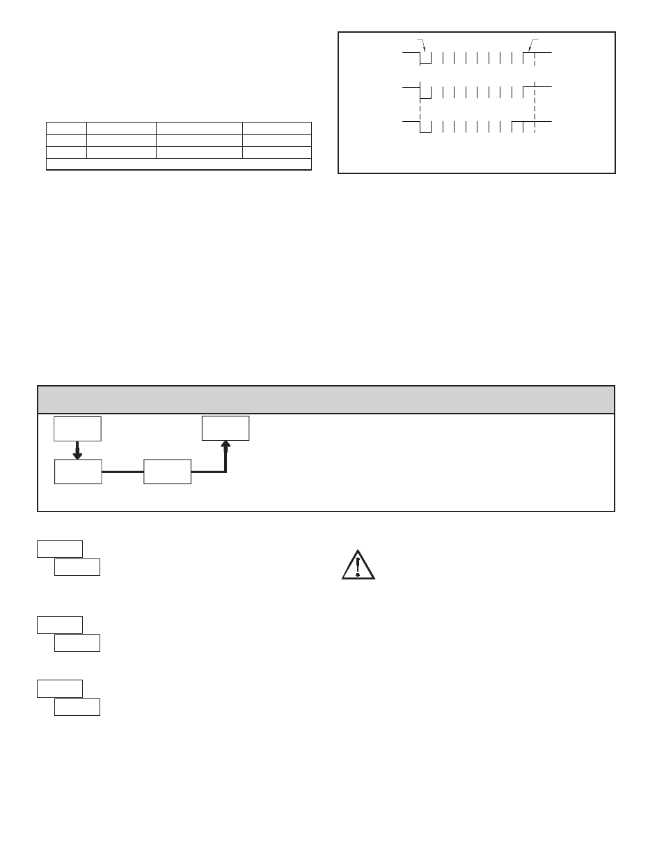
Data is transmitted one byte at a time with a variable idle period between
characters (0 to ∞). Each ASCII character is “framed” with a beginning start bit,
an optional error detection parity bit and one or more ending stop bits. The data
format and baud rate must match that of other equipment in order for
communication to take place. The figures list the data formats employed by
the meter.
Start bit and Data bits
Data transmission always begins with the start bit. The start bit signals the
receiving device to prepare for reception of data. One bit period later, the least
significant bit of the ASCII encoded character is transmitted, followed by the
remaining data bits. The receiving device then reads each bit position as they are
transmitted. Since the sending and receiving devices operate at the same
transmission speed (baud rate), the data is read without timing errors.
Parity bit
After the data bits, the parity bit is sent. The transmitter sets the parity bit to
a zero or a one, so that the total number of ones contained in the transmission
(including the parity bit) is either even or odd. This bit is used by the receiver
to detect errors that may occur to an odd number of bits in the transmission.
However, a single parity bit cannot detect errors that may occur to an even
number of bits. Given this limitation, the parity bit is often ignored by the
receiving device. The meter ignores the parity bit of incoming data and sets the
parity bit to odd, even or none (mark parity) for outgoing data.
Stop bit
The last character transmitted is the stop bit. The stop bit provides a single bit
period pause to allow the receiver to prepare to re-synchronize to the start of a
new transmission (start bit of next byte). The receiver then continuously looks
for the occurrence of the start bit.
IDLE 0 b
0
1
b
2
b b
3
b
4
b
5
6
b
1 IDLE
IDLE
IDLE 0
b
b
0
b
1
3
2
b b
4
b
5
b
6
P 1
IDLE
IDLE 0
b
b b
0
1
b
b
3
2
4
b
b
5
6
1 1
(7 data, no parity, 2 stop)
(7 data, parity, 1 stop)
(8 data, no parity, 1 stop)
Start bit
Stop bit
Note: b - b is ASCII data.
0
7
7
b
Character Frame Figure
LOGIC
RS232*
RS485*
INTERFACE STATE
1
TXD,RXD; -3 to -15 V
a-b < -200 mV
mark (idle)
0
TXD,RXD; +3 to +15 V
a-b > +200 mV
space (active)
* Voltage levels at the Receiver
d-LEV
Display
Intensity Level
PAR
9-FCS
Pro
Factory
Service Code
COdE
6.9 Module 9 - F
actory
s
ervIce
o
peratIons
(
)
PARAMETER MENU
Enter the desired Display Intensity Level (0-15) by
using the arrow keys. The display will actively dim or
brighten as the levels are changed. This parameter also
appears in Quick Programming Mode when enabled.
DISPLAY INTENSITY LEVEL
The meter has been fully calibrated at the factory.
Scaling to convert the input signal to a desired display
value is performed in Module 1. If the meter appears to be
indicating incorrectly or inaccurately, refer to
Troubleshooting before attempting to calibrate the meter.
When recalibration is required (generally every 2 years), it should only be
performed by qualified technicians using appropriate equipment. Calibration
does not change any user programmed parameters. However, it may affect the
accuracy of the input signal values previously stored using the Apply (
)
Scaling Style.
Calibration may be aborted by disconnecting power to the meter before
exiting Module 9. In this case, the existing calibration settings remain in effect.
CALIBRATION
RESTORE FACTORY DEFAULTS
Use the arrow keys to display
and press
PAR.
The meter will display
and then return to
.
Press
DSP key to return to Display Mode. This will
overwrite all user settings with the factory settings.
Input Calibration
WARNING: Calibration of this meter requires a signal source with an
accuracy of 0.01% or better and an external meter with an accuracy
of 0.005% or better.
Before starting, connect -SIG (terminal 3) to COMM (terminal 4).
This allows a single ended signal to be used for calibration. Connect the
calibration signal to +SIG (terminal 2) and -SIG (terminal 3). Verify the Input
Range jumper is in the desired position. Allow a 30 minute warm-up period
before calibrating the meter.
and
PAR can be chosen to exit the calibration
mode without any changes taking place. Perform the following procedure:
1. Press the arrow keys to display
and press
PAR.
2. Choose the range to be calibrated by using the arrow keys and press
PAR.
3. When the zero range limit appears on the display, apply 0 mV between +SIG
and -SIG.
4. Press
PAR and ---- will appear, wait for next prompt.
5. When the top range limit appears on the display, apply the corresponding
+SIG and -SIG voltage (20 mV or 200 mV).
6. Press
PAR and ---- will appear, on the display for about 10 seconds.
7. When
appears, press
PAR twice to exit programming.
8. Repeat the above procedure for each range to be calibrated or to recalibrate
the same range. It is only necessary to calibrate the input ranges being used.
9. When all desired calibrations are completed, remove -SIG to COMM
connection and external signal source.
10. Restore original configuration and jumper settings.