Transmitter structure, Figure 1 – Vaisala MMT162 User Manual
Page 13
Chapter 2 __________________________________________________________ Product Overview
VAISALA _______________________________________________________________________ 11
Transmitter Structure
The structure of the MMT162 is shown in Figure 1 on page 11. The
transmitter body does not have user serviceable parts inside, and is not
designed to be opened. Opening the transmitter will void the warranty.
When the transmitter is delivered, the filter is protected by a yellow
transport protection cap. Remove the transport protection cap before
installing the transmitter.
0805-007
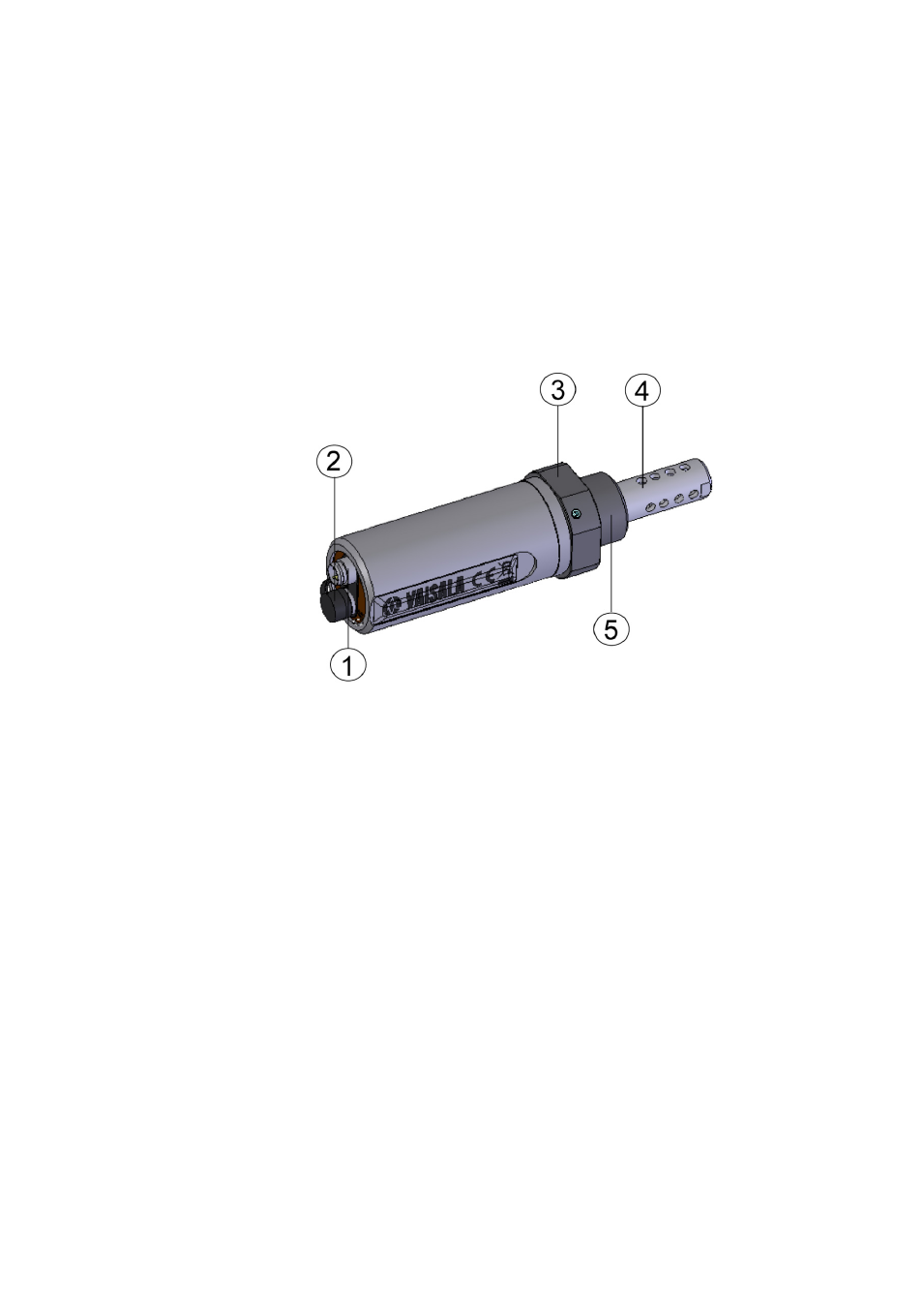
Figure 1
Moisture and Temperature Transmitter for Oil
MMT162
where
1 = 4-pin M8 connector I: analog output channels and operating
power
2 = 4-pin M8 connector II (shown with protective cap):
digital output (RS-485) and operating power
3 = 30 mm nut
4 = HUMICAP
®
sensor protected with stainless steel grid filter
5 = Connection thread: ISO G1/2" or NPT 1/2"