Features and components – State SBD85 365NE A User Manual
Page 7
7
features and components
the hydrocannon (self-cleaning system)
These units include The Hydrocannon (Self-Cleaning System)
installed in the front water inlet, See Figure 1. The Hydrocannon
inlet tube can only be used in the front water inlet connection. Do
not install the Hydrocannon inlet tube in either the top or back inlet
water connection. The Hydrocannon must be oriented correctly for
proper function. There is a marked range on pipe nipple portion
of the Hydrocannon, that must be aligned with top of inlet spud. A
label above the jacket hole has an arrow that will point to marked
portion of pipe nipple if the orientation is correct. If the arrow does
not point within the marked range on pipe nipple, adjust the pipe
nipple to correct. A pipe union is supplied with the Hydrocannon
to reduce probability of misaligning the Hydrocannon accidentally
while tightening the connection to inlet water supply line. Improper
orientation of the Hydrocannon can cause poor performance of
heater and can significantly reduce outlet water temperatures
during heavy draws.
note: the hydrocannon may have 1, 3 or 7 cross tubes.
figure 1.
high limit switch
The digital thermostat (Figure 2) contains the high limit (energy
cutout) switch. The high limit switch interrupts main burner gas flow
should the water temperature reach 203°F (95°C).
In the event of high limit switch operation, the water heater cannot be
restarted unless the water temperature is reduced to approximately
120°F (49°C). The high limit reset button on the front of the control
then needs to be depressed.
Continued manual resetting of high limit control, preceded by higher
than usual water temperature is evidence of high limit switch operation.
The following is a possible reason for high limit switch operation:
• A malfunction in the thermostatic controls would allow the
gas control valve to remain open causing water temperature
to exceed the thermostat setting. The water temperature
would continue to rise until high limit switch operation.
Contact your dealer or service agent if continued high limit switch
operation occurs.
digital thermostat
figure 2.
electronic ignition control
Each heater is equipped with a Honeywell ignition module. The
solid state ignition control ignites the pilot burner gas by
creating a spark at the pilot assembly. See Figure 3. Pilot
gas is ignited and burns during each running cycle. The main
burner and pilot gases are cut off during the OFF cycle.
Pilot gas ignition is proven by the pilot sensor. Main burner
ignition will not occur if the pilot sensor does not first sense
pilot ignition.
ignition module
figure 3.
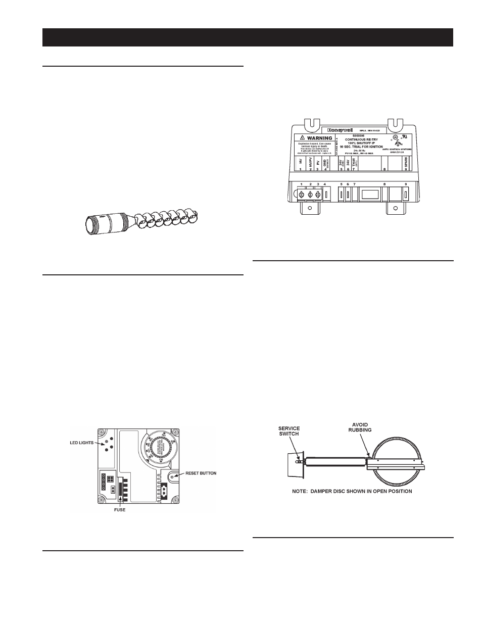
automatic flue damper
All units are equipped with an automatic flue damper that
reduces heat loss during the OFF cycles.
Each automatic flue damper drive assembly is equipped with a
“Service Switch”, as shown in Figure 4
The “Ser vice Switch” has 2 positions: AUTOMATIC
OPERATION and HOLD OPEN DAMPER. For normal operation
the switch should be in the AUTOMATIC OPERATION position.
If there is a problem with the damper the “Service Switch”
can be placed in the HOLD OPEN DAMPER position. When
the switch is placed in the HOLD OPEN DAMPER position
the damper disc will rotate to the open position and the
heater may be used until vent assembly is repaired or
replaced. DO NOT turn the damper disc manually; damage
will occur to the drive assembly if operated manually. Refer
to TESTING DAMPER OPERATION section of this manual
for additional information.
flue damper
figure 4.
uncrating
The heater is shipped with the flue damper already installed. The
wiring conduit runs from the thermostat to the damper drive cover.
Before turning unit on, check to make sure the wiring conduit is
securely plugged into damper drive.