Heater wiring, Figure 20 – State SBD85 365NE A User Manual
Page 23
23
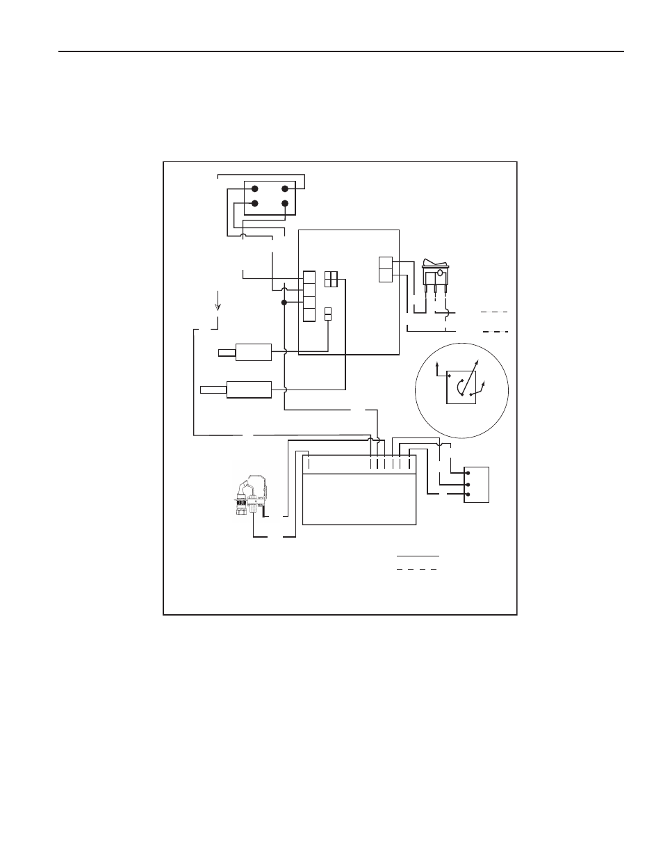
heater wiring
All electrical work must be installed in accordance with the current edition of the National Electrical Code ANSI/NFPA No. 70 or Canadian Electrical
Code CSA C22.1 and must conform to all local code authority having jurisdiction. AN ELECTRICAL GROUND IS REQUIRED TO REDUCE RISK OF
ELECTRICAL SHOCK OR POSSIBLE ELECTROCUTION.
If any of the original wire as supplied with the water heater must be replaced, use only type 105°C thermoplastic or equivalent 250
0
C type F must be
used for the flame sensor and igniter leads.
The controls of this water heater are polarity sensitive. Be certain to properly wire the hot and neutral connections.
1 3
4 2
C
P
M
X
MV
MV/PV
PV
24 V GND
24 V
SP
ARKER
GND-BURNE
R
HONEYWELL IGNITION
DAMPER
DRIVE
ON/OFF
SWITCH
LOWER
PROBE
UPPER
PROBE/ECO
11E79
LINE
IN
1
2
3
4
NEUTRAL
NATURAL
GAS
VALVE
PV
PV
TH TR
MV
MV/PV
MV
PROPANE
GAS
VALVE
120 vac
24
VA
C
TO
IGNITION CONTRO
L
DAMPER
DRIVE
24
VA
C
24 NEUTRAL
FACTORY WIRED
BY INSTALLER
IF ANY OF THE ORIGINAL WIRE AS SUPPLIED MUST BE REPLACED, USE ONLY TYPE 105
O
C
THERMOPLASTIC OR EQUIVALENT. FLAME SENSOR IGNITION CABLE MUST BE 250
O
C TYPE F.
197287-000 REV 02
W
W
W
Y
BLK
BLK
BLK
W
R
R
Y
BLK
BL
BL
LEGEND:
W--WHITE
BLK--BLACK
BL--BLUE
R--RED
Y--YELLOW
figure 20.