Troubleshooting – State SBD85 365NE A User Manual
Page 36
36
receptacle. Do not push meter leads into harness receptacle.
This opens the pins and will create connection problems. See
the following EFFIKAL RVGP-KSF-SERIES FLUE DAMPER
TROUBLE SHOOTING GUIDE.
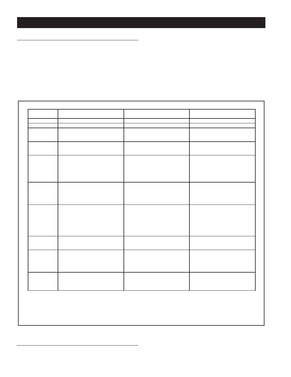
Green LED
Flash Code
a
Indicates
Next System Action
Recommended Service Action
OFF
No “Call for Heat”
Not applicable
None
Flash Fast
Power up - internal check
Not applicable
None
Heartbeat
Norma l startup – ignition
sequence started (including
prepurge)
Not applicable
None
4 Seconds
ON then “x”
flashes
Device in run mode. “x” = flame
current to the nearest μ A.
Not applicable
None
2
5 minute Retry Delay - Pilot flame
not detected during trial for ignition
Initiate new trial for ignition after
retry delay completed.
If system fails to light on next trial
for ignition check gas supply, pilot
burner, spark and flame sense
wiring, flame rod contaminated or
out of position, burner ground
connection.
3
Recycle - Flame failed during run
Initiate new trial for ignition. Flash
code will remain through the
ignition trial until flame is proved.
If system fails to light on next trial
for ignition, check gas supply, pilot
burner, flame sense wiring,
contamination of flame rod, burner
ground connection.
4
Flame sensed out of sequence
If situation self corrects within 10
seconds, control returns to normal
sequence. If flam e out of
sequence remains longer than 10
seconds, control will resume
normal operation 1 hour after error
is corrected.
Check for pilot flame. Replace gas
valve if pilot flame present. If no
pilot flame, cycle “Call for Heat.” If
error repeats, replace con trol.
6
Control Internal Error
Control remains in wait mode.
When the fault corrects, control
resumes normal operation.
Cycle “Call for Heat”. If error
repeats, replace control.
7
Flame rod shorted to ground
Control remains in wait mode.
When the fault corrects, control
resumes normal operation.
Check flame sense lead wire for
damage or shorting. Check that
flame rod is in proper position.
Check flame rod ceramic for
cracks, damage or tracking.
8
Low secondary voltage supply
Control remains in wait mo de.
When the fault corrects, control
resumes normal operation.
Check transformer and AC line for
proper input voltage to the control.
Check with full system load on the
transformer.
a
Flash Code Descriptions:
- Flash Fast: rapid blinking.
- Heartbeat: Constant ½ second bright, ½ second dim cycles.
- 4 second solid on pulse followed by “x” 1 second flashes indicates flame current to the nearest μ A. This is only available in run mode.
- A single flash code number signifies that the LED flashes X times at 2H z, remains off for two seconds, and then repeats the sequence.
ignition module
Before calling your service agent, the following checklist should
be examined to eliminate obvious problems from those requiring
replacement or servicing.
• Check that “main manual gas shut-off valve” is fully open
and that gas service has not been interrupted.
• Check that after following the water OPERATING
INSTRUCTIONS, the “Top Knob” of the gas control valve
is in “ON” position.
• Check electrical supply to the water heater for possible
blown (or tripped) fusing or power interruption.
• Is the water temperature in tank below the thermostat dial
setting on the thermostat (calling for heat)?
• It is possible that the high limit (E.C.O.) has functioned to shut
off the water heater. See FEATURES - Water Temperature
Control for reset procedure. Contact your serviceman if limit
continues to function to shut off water heater.
flue damper
Do not turn damper open manually or motor damage will result,
use the service switch. All readings are taken from harness
trouBleshooting