State SBD85 365NE A User Manual
Page 14
14
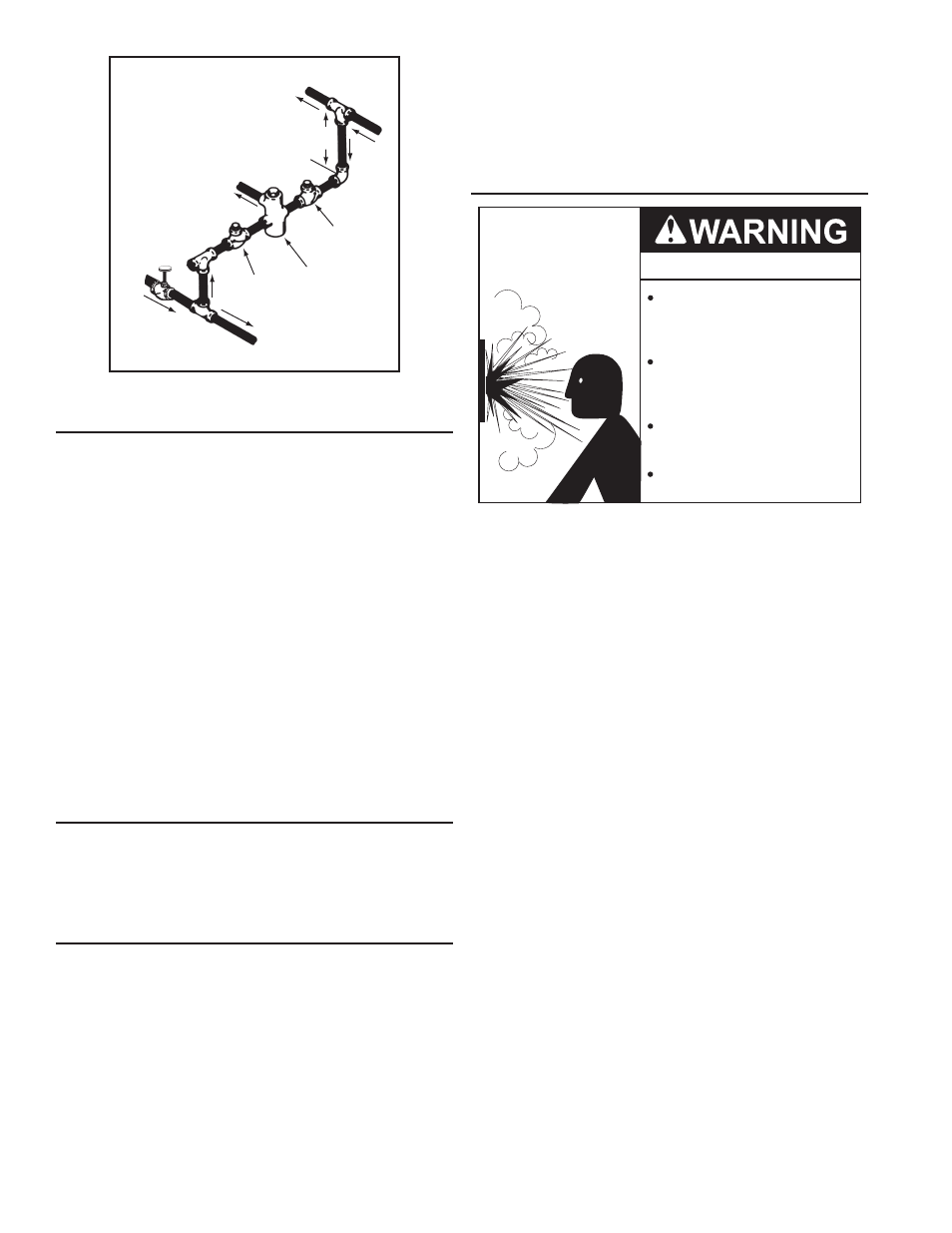
HOT WATER
OUTLET
TO TANK
INLET
CHECK
VALVE
MIXING
VALVE
COLD
WATER
INLET
TEMPERED WATER
OUTLET
12” TO 15”
(30-38 cm)
CHECK
VALVE
figure 10.
dishwashing machines
All dishwashing machines meeting the National Sanitation
Foundation requirements are designed to operate with water flow
pressures between 15 and 25 pounds per square inch (103 kPa
and 173 kPa). Flow pressures above 25 pounds per square inch
(173 kPa), or below 15 pounds per square inch (103 kPa), will
result in improperly sanitized dishes. Where pressures are high,
a water pressure reducing or flow regulating control valve should
be used in the 180°F (82°C) line to the dishwashing machine and
should be adjusted to deliver water pressure between these limits.
The National Sanitation Foundation also recommends circulation
of 180°F (82°C) water. The circulation flow rate should be just
enough to provide 180°F (82°C) water at the point of take-off to
the dishwashing machine.
Adjust flow by throttling a full port ball valve installed in the
circulating line on the outlet side of the pump. Never throttle flow
on the suction side of a pump. See Water Piping Diagrams in
this manual.
note: These water heaters meet the NSF Standard 5 for
sanitary installations when used with the leg kit part number
9003425205.
closed water systems
Water supply systems may, because of code requirements
or such conditions as high line pressure, among others, have
installed devices such as pressure reducing valves, check
valves, and back flow preventers. Devices such as these cause
the water system to be a closed system.
thermal eXpansion
As water is heated, it expands (thermal expansion). In a closed
system the volume of water will grow when it is heated. As the
volume of water grows there will be a corresponding increase
in water pressure due to thermal expansion. Thermal expansion
can cause premature tank failure (leakage). This type of failure
is not covered under the limited warranty. Thermal expansion
can also cause intermittent Temperature-Pressure Relief Valve
operation: water discharged from the valve due to excessive
pressure build up. This condition is not covered under the limited
warranty. The Temperature-Pressure Relief Valve is not intended
for the constant relief of thermal expansion.
A properly sized thermal expansion tank must be installed on
all closed systems to control the harmful effects of thermal
expansion. Contact a local plumbing service agency to have a
thermal expansion tank installed.
See Water Line Connections on page 21 and the Water Piping
Diagrams beginning on page 40.
temperature-pressure relief ValVe
Explosion Hazard
Temperature-Pressure Relief Valve
must comply with ANSI Z21.22-
CSA 4.4 and ASME code.
Properly sized temperature-
pressure relief valve must be
installed in opening provided.
Can result in overheating and
excessive tank pressure.
Can cause serious injury or death.
This water heater is provided with a properly rated/sized and certified
combination Temperature-Pressure Relief Valve (T&P valve) by
the manufacturer. The valve is certified by a nationally recognized
testing laboratory that maintains periodic inspection of production
of listed equipment of materials as meeting the requirements for
Pressure Relief Valves for Hot Water Supply Systems, ANSI Z21.22
• CSA 4.4, and the code requirements of ASME.
If replaced, the new T&P valve must meet the requirements
of local codes, but not less than a combination Temperature-
Pressure Relief Valve rated/sized and certified as indicated in
the above paragraph. The new valve must be marked with a
maximum set pressure not to exceed the marked hydrostatic
working pressure of the water heater (150 psi = 1,035 kPa) and
a discharge capacity not less than the water heater Btu/hr or kW
input rate as shown on the water heater’s model rating label.
NOTE: In addition to the factory installed Temperature-Pressure
Relief Valve on the water heater, each remote storage tank that
may be installed and piped to a water heating appliance must also
have its own properly sized, rated and approved Temperature-
Pressure Relief Valve installed. Call the toll free technical
support phone number listed on the back cover of this manual
for technical assistance in sizing a Temperature-Pressure Relief
Valve for remote storage tanks.
For safe operation of the water heater, the Temperature-Pressure
Relief Valve must not be removed from its designated opening
nor plugged. The Temperature-Pressure Relief Valve must be
installed directly into the fitting of the water heater designed for
the pressure relief valve . Install discharge piping so that any
discharge will exit the pipe within 6 inches (15.2 cm) above an
adequate floor drain, or external to the building. In cold climates
it is recommended that it be terminated at an adequate drain
inside the building. Be certain that no contact is made with any
live electrical part. The discharge opening must not be blocked
or reduced in size under any circumstances. Excessive length,
over 30 feet (9.14 m), or use of more than four elbows can cause
restriction and reduce the discharge capacity of the valve.