Service – State SBD85 365NE A User Manual
Page 35
35
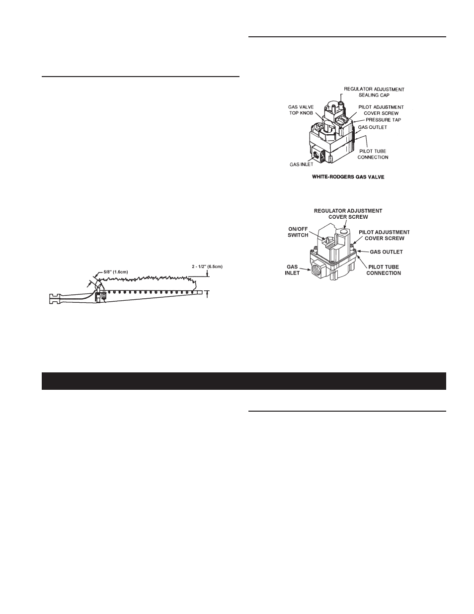
gas control ValVe
Figure 31 shows the two types of combination gas control valves
used on these heaters.
If gas control valve becomes defective, repairs should not be
attempted. A new valve should be installed in place of defective one.
lp ValVe
natural ValVe
figure 31.
The installer may be able to observe and correct certain problems
which may arise when the unit is put into operation. HOWEVER,
it is recommended that only a qualified service technician or
qualified agencys, using appropriate test equipment, be allowed
to service the heater.
As preliminary step, check wiring against diagram, check for
grounded, broken or loose wires. Check all wire ends to be sure
that they are making good contact.
electrical serVicing
LABEL ALL WIRES PRIOR TO DISCONNECTION WHEN SERVICING
CONTROLS. WIRING ERRORS CAN CAUSE IMPROPER AND
DANGEROUS OPERATION.
VERIFY PROPER OPERATION AFTER SERVICING.
Pilot sensing device must sense a flame before sparking will stop.
Loose wires or a draft may cause intermittent or abnormal
sparking. To eliminate this condition, first correct loose wiring
condition, and then, if necessary, increase pilot flame.
main Burner
The main burner, Figure 30, should display the following
characteristics:
• Cause rapid ignition and carry over of flame across entire burner.
• Give reasonably quiet operation during ignition, burning and extinction.
• Cause no excessive lifting of flame from burner ports.
If the preceding burner characteristics are not evident, check for
accumulation of lint or other foreign material that restricts or other
foreign material that restricts or blocks air openings to burner or heater.
To clean main burners:
1. Remove main burners from unit.
2. Check that burner venturi and ports are free of foreign matter.
3. Clean burners with bristle brush and/or vacuum cleaner
DO NOT distort burner ports or pilot location.
4. Reinstall burners in unit. Make sure front and rear of burners
are installed correctly in burner support brackets.
Also check for good flow of combustion and ventilating air to the unit.
typical pilot and main Burner flames
figure 30.
serVice