State GPG 81 370NEA User Manual
Page 26
26
adjustments
1. Check gas line pressure and manifold pressure (Table 9) and
adjust as required.
2. Check barometric damper for proper operation. Parts must
move freely.
3. Allow the unit to operate for 15 minutes. Drain hot water from
the heater or storage tank to continue main burner operation.
4. Determine heat input rate (see CHeCkING THe INPuT
section below).
checking Venting
The following steps shall be followed with each appliance
connected to the venting system placed in operation, while
any other appliances connected to the venting system are
not in operation.
1. Seal any unused openings in the venting system.
2. Inspect the venting system for proper size and horizontal
pitch, as required in the National Fuel Gas Code, ANSI
Z223.1or the CAN/CGA B149 Installation Codes and
these instructions. Determine that there is no blockage or
restriction, leakage, corrosion and other deficiencies which
could cause an unsafe condition.
3. So far as is practical, close all building doors and windows
and all doors between the space in which the water
heater(s) connected to the venting system are located and
other spaces of the building. Turn on all appliances not
connected to the venting system. Turn on all exhaust fans,
such as range hoods and bathroom exhausts, so they shall
operate at maximum speed. Close fireplace dampers.
4. Follow the lighting instruction. Place the water heater in
operation. Adjust thermostat so water heater shall operate
continuously.
5. After it has been determined that each appliance connected
to the venting system properly vents when tested as outlined
above, return doors, windows, exhaust fans, fireplace
dampers and any other gas burning appliance to their
previous conditions of use.
6. If improper venting is observed during any of the above
tests, the venting system must be corrected.
FAIlure TO COrreCT BACk DrAFTS mAy CAuSe AIr
CONTAmINATION AND uNSAFe CONDITIONS.
• If the back draft cannot be corrected by the normal method
or if a suitable draft cannot be obtained, a blower type flue
gas exhauster must be employed to assure proper venting
and correct combustion.
checking the input
For installation locations with elevations above 2000 feet, refer
to HIGH AlTITuDe INSTAllATIONS section of this manual
for input reduction procedure.
The input rate can be estimated by timing the meter, if no other
appliances are operating.
With a stopwatch, or a wristwatch, which can display the time
in seconds, read the gas meter and measure the amount of
time required for the heater to consume 5 cubic feet of gas. The
actual rate may then be estimated by using the formula below:
(3600/T) x H = Btuh
T = Time in seconds to burn one cubic foot of gas.
H = Btu’s per cubic foot of gas.
Btuh = Actual heater input.
example:
T = 15.1 seconds
H = 1050 Btu
Btuh = ?
(3600/15.1) x 1050 = 250,000
The input may be adjusted by adjusting the pressure regulator.
remove the top cap to expose the adjustment screw. Turning
the screw in increases the gas pressure and backing the
screw out decreases the pressure. Do not turn the adjusting
screw in past the point where no further increase in pressure
is noted.
The manifold pressure is measured at the line Pressure Tap,
see Figure 22, and should be used as a reference point for
making pressure regulator adjustments. Table 9 gives the
design manifold pressures for each model. Increase or reduce
the pressure as required to obtain the rated input.
If an acceptable rate cannot be achieved by adjusting the
pressure regulator (manifold pressure), first check to be
certain that the gas supply pressure to the unit is adequate.
If the supply pressure is inadequate, a different burner orifice
may be required. Obtain from the utility the heating value and
specific gravity of the gas at the site. Provide this information
and the altitude of the site to obtain a larger orifice size.
uNDer NO CIrCumSTANCeS SHOulD THe GAS INPuT
eXCeeD THe INPuT SHOWN ON THe HeATer mODel AND
rATING PlATe. OVerFIrING COulD reSulT IN DAmAGe
Or SOOTING OF THe HeATer.
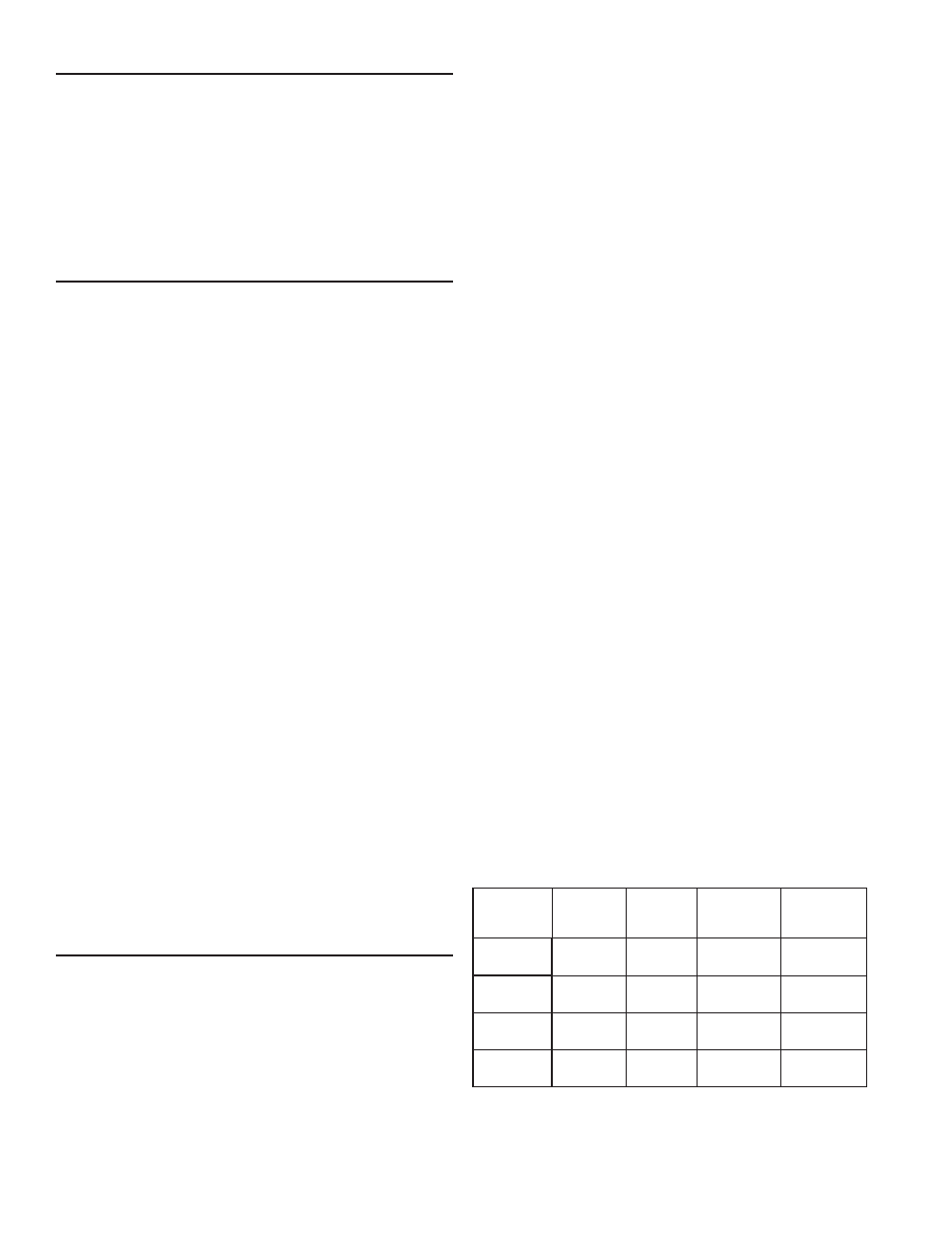
table 8.
approXimate time reQuired to consume
1 cu. ft. of gas at full capacity
input
rate
(btuh)
input
btuh
per
cu. ft.
times
(for natural
gas in sec.)
times
(for lp gas
in sec.)
GPG 81-140
140000
1050
2500
27. 2
64.7
GPG 81-199
199000
1050
2500
19.0
45.2
GPG 81-270
270000
1050
2500
14.0
33.3
GPG 81-370
370000
1050
2500
10.2.
24.3