Caution – State GPG 81 370NEA User Manual
Page 20
20
This water heater is provided with a properly rated/sized and
certified combination temperature - pressure (T&P) relief valve
by the manufacturer. See Temperature-Pressure relief Valve
on pages 14-15 for information on replacement and other
requirements.
Water Damage Hazard
Temperature-Pressure Relief Valve discharge
pipe must terminate at adequate drain.
•
CAUTION
Install a discharge pipe between the T&P valve discharge
opening and a suitable floor drain. Do not connect discharge
piping directly to the drain unless a 6” (15.2 cm) air gap is
provided. To prevent bodily injury, hazard to life, or property
damage, the relief valve must be allowed to discharge water
in adequate quantities should circumstances demand. If the
discharge pipe is not connected to a drain or other suitable
means, the water flow may cause property damage.
t&p ValVe discharge pipe reQuirements:
• Shall not be smaller in size than the outlet pipe size of the
valve, or have any reducing couplings or other restrictions.
• Shall not be plugged or blocked.
• Shall not be exposed to freezing temperatures.
• Shall be of material listed for hot water distribution.
• Shall be installed so as to allow complete drainage of both
Temperature-Pressure relief Valve and the discharge pipe.
• must terminate a maximum of six inches above a floor
drain or external to the building. In cold climates, it is
recommended that the discharge pipe be terminated at an
adequate drain inside the building.
• Shall not have any valve or other obstruction between the
relief valve and the drain.
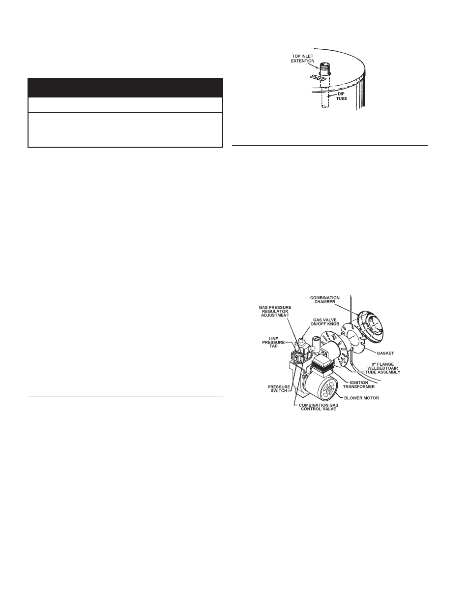
installation diagrams - top inlet/outlet usage
use of the top inlet water connection requires an inlet dip tube
(refer to Figure 17). The tube is supplied in the heater. Follow
caution labels if applying heat to this fitting. Do not allow pipe
dope to contact the plastic tube during installation.
tube inlet installation
figure 17.
burner installation
remove the factory-installed insulation covering the combustion
chamber opening. (A utility knife is useful for cutting out the
insulation). Cut the insulation back even with the jacket opening.
Install the flange gasket (which is usually taped to the heater jacket)
over the three bolts protruding from the tank at the combustion
chamber opening.
remove hardware (3 hex nuts, 3 flat washers, and 3 lock washers)
from the shipping bag attached to the heater’s electrical conduit.
Begin assembling the power burner to the tank by placing the power
burner nozzle in the combustion chamber opening. Slide the nozzle
into the tank and rotate the mounting flange to engage the mounting
bolts, refer to Figure 18. Then, place the flat washers followed by
the lock washers, and finally the hex nuts on the mounting bolts.
Hand tighten the nuts. Then gradually tighten each nut alternating
between the 3 mounting bolts. Do not over tighten as damage to
the flange gasket or to the tank may result. refer to Figure 18.
power burner installation
figure 18.