Reference parts listing – State GS6 75 YRVHTL User Manual
Page 50
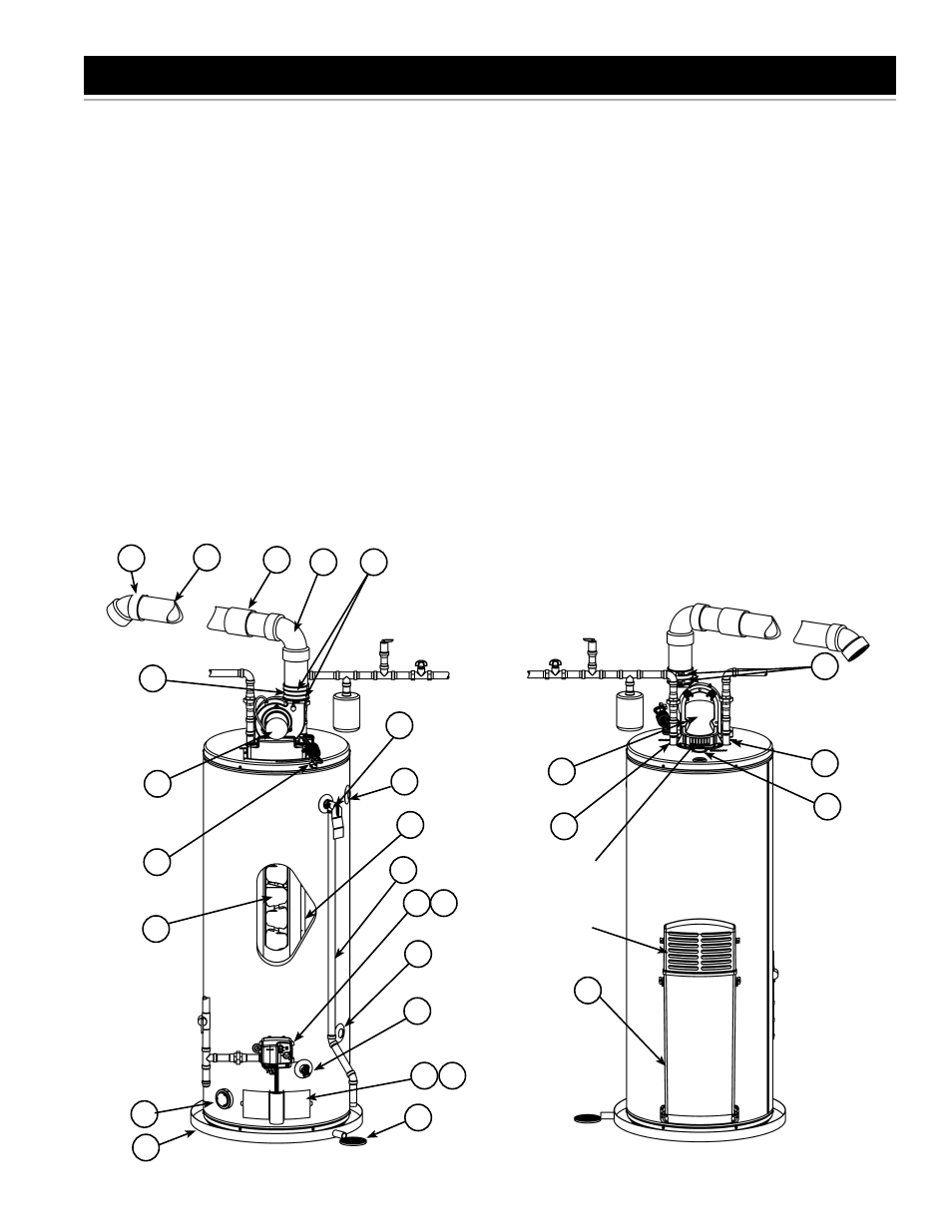
REFERENCE PARTS LISTING
Replacement parts may be ordered
through your plumber or the local
distributor. When ordering replacement
parts, always have the following
information ready:
1. Model, Serial and Product number
2. Type of gas
3. Item
number
4. Parts
description
1. Vent Termination Elbow with Rodent
Screen
2. **Vent Pipe
3. **Vent Pipe Coupling (if required)
4. **Vent Pipe Elbow (long radius)
5. Blower High Limit Switch (see
Figure 61)
6. T&P Valve
7. Cold-Water Inlet Nipple/Diptube
8. Baffl e Assembly
9. ** Discharge Pipe
10. Gas Control Valve/Thermostat
(Honeywell)
11. Gas Valve Electronic Control
Module And Cover (Honeywell)
12. Drain Valve
13. Outer Gas Door
14. Manifold Door Assembly (behind
outer door) (see Figure 58 & Figure
59)
15. **Floor Drain
16. **Metal Drain Pan
17. Flammable Vapor Sensor (under
cover) (see Figure 60)
18. Combo Heating System Return
Inlet (Optional)
19. Air Inlet Snorkel
20. Combo Heating System Supply
Outlet (Optional)
21. Blower with Power Cord (see also
Figure 61)
22. Air Switch (inside box) (see
Figure 61)
23. Junction Box (see Figure 61)
24. Junction Box Cover (see Figure 61)
25. Air Tubing (see Figure 61)
26. Rubber Coupling (see also
Figure 61)
27. Gear Clamp (see also Figure 61)
28. Flue Collector
29. Hot-Water Outlet Nipple
30. Anode (under cap)
32. Flexible Manifold Tube (see
Figure 58 & Figure 59)
33. Vi e w p o r t ( s e e F i g u r e 5 8 &
Figure 59)
34. Flame Sensor Rod (see Figure 58
& Figure 59)
35. Gas Orifice (see Figure 58 &
Figure 59)
36. Sheet Metal Burner (see Figure 58
& Figure 59)
37. Gas Manifold (see Figure 58 &
Figure 59)
38. Hot-Surface Igniter (see Figure 58
& Figure 59)
39. Manifold Door Gasket (see
Figure 58 & Figure 59)
40. Manifold Door (see Figure 58 &
Figure 59)
41. Two Piece Grommet With Clip
(Figure 58 & Figure 59)
** parts not supplied with the water
heater
Front View
Rear View
Figure 56.
Figure 57.
1
6
9
10
12
13
16
17
20
18
2
3
4
21
27
21
8
7
14
11
15
26
19
28
29
7
30
Combustion
Air Inlets
27
Blower
Dilution Air
Inlets
50 www.statewaterheaters.com