Warning, Figure 11 – State GS6 75 YRVHTL User Manual
Page 13
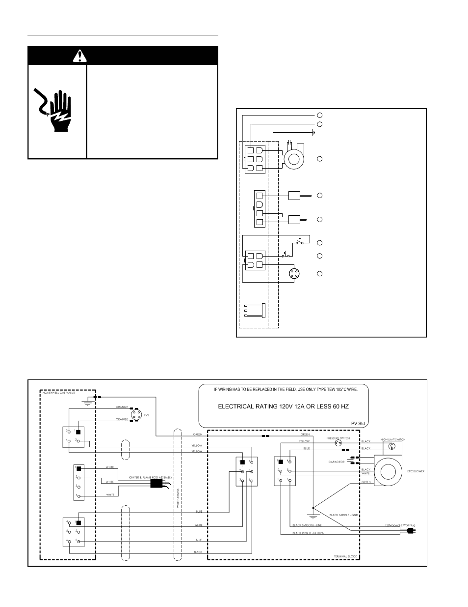
Figure 12.
ELECTRICAL REQUIREMENTS & WIRING DIAGRAM
Failure to do so can result in
death or electrical shock.
Replace all parts and panels
before operating.
Disconnect power before
servicing.
Electric Shock Hazard
WARNING
Before plugging in the water heater, always make sure:
•
The voltage and frequency correspond to that
specifi ed on the water heater wiring diagram.
•
The electrical outlet has the proper overload fuse or
breaker protection.
1. The unit must be connected to a dedicated power
supply.
2. The unit must be connected to a 120VAC power
supply.
3. The water heater must be properly grounded.
4. This water heater is a polarity sensitive appliance and
will not operate if the power supply polarity is reversed.
Note: Always reference the wiring diagram for the correct
electrical connections.
After making all electrical connections, completely fi ll the
tank with water and check all connections for leaks. Open
the nearest hot-water faucet and let it run for 3 minutes to
purge the water lines of air and sediment and to ensure
complete fi lling of the tank. The electrical power may then
be turned on. Verify proper operation after servicing. See
also “Installation Checklist”.
CAUTION
LABEL ALL WIRES PRIOR TO DISCONNECTION WHEN
SERVICING CONTROLS. WIRING ERRORS CAN
CAUSE IMPROPER AND DANGEROUS OPERATION.
VERIFY PROPER OPERATION AFTER SERVICING.
POWER VENT WIRING SCHEMATIC.
NOTE: REFER TO THE “INSTALLATION CHECKLIST”
BEFORE OPERATING THIS HEATER.
N
1
2
3
HOT SURFACE IGNITER
HIGH LIMIT SWITCH
CAPACITOR
L1
EARTH GND
PRESSURE SWITCH
BLOWER
4
5
6
4
3
2
1
2
1
3
4
FLAME SENSOR
FLAMMABLE VAPOUR SENSOR
P1
P2
P3
4
6
1
5
3
2
7
Circled numbers indicate
sequence of operation.
P4
1
Figure 11.
www.statewaterheaters.com
13