Safety lockouts – State GS6 75 YRVHTL User Manual
Page 14
This water heater has several lockout features designed
to prevent the heater from operating in unsafe conditions.
HIGH LIMIT CONTROLS (Energy Cut Off)
Thermostat/Water Temperature
This feature is a part of the gas control valve/thermostat
(see Figure 1, item 10) and limits the maximum water
temperature. In the event of the water overheating, this
safety feature shuts off the fuel supply to the burner.
Blower High Limit Switch
This device is located on the blower (see Figure 6, item
5) and limits the maximum temperature of the blower.
If the blower temperature rises above the temperature
setting, the switch opens causing the heater to shut down.
The switch will auto reset once the temperature drops
suffi ciently.
BLOWER AIR PRESSURE SWITCH
This device, located in the junction box, monitors the air
pressure produced by the blower. In the event that the
exhaust venting becomes blocked or suffi ciently restricted,
the switch will shut the heater down (see Figure 6, item 22).
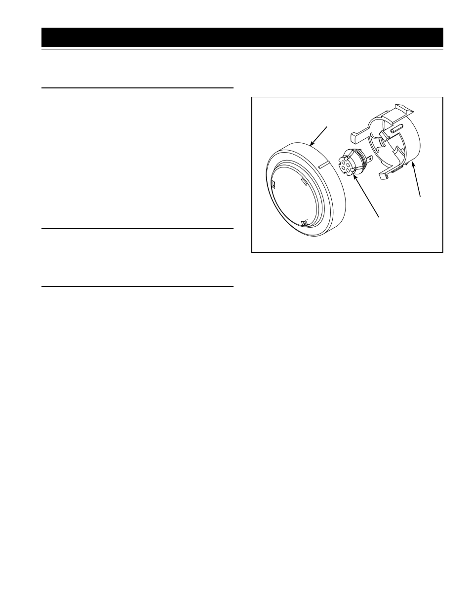
FLAMMABLE VAPOR SENSOR
When using a gas fi red water heater there is a risk of
fl ammable vapors entering the combustion chamber, being
ignited by the burner fl ame and causing a fl ashback. In
order to detect such fl ammable vapors before they enter
the combustion chamber, this water heater is equipped
with a fl ammable vapor sensor (FVS). It is a chemical-
absorption based sensor that is connected to the gas
control/thermostat (see Figure 13). When exposed to
fl ammable vapors it will trigger the control to stop the
fl ow of gas and enter the FVS lockout state. While in the
FVS lockout state the LED on the control will fl ash the
gas lockout code. (Refer to the “System Status And Error
Codes” section of this manual for an explanation of the
codes applicable to the control installed on your water
heater.) If this error occurs, check around the water heater
for sources of chemical contamination such as: fl ammable
vapors including gas vapors, solvents, paint and thinners
as well as sources of water and detergents.
Note: Resetting the heater will reset the FVIR circuit if
all sources of contamination have been removed and the
sensor clears. If all sources of contamination have been
removed and the system will not reset, the sensor will need
to be replaced (see “Resetting the Heater Control”).
If there is a problem with the wiring of the fl ammable
vapor sensor or the fl ammable vapor interface, the LED
will fl ash the failure status code (see “System Status And
Error Codes”).
MOUNTING
BRACKET
FLAMMABLE
VAPOR SENSOR
(PULL TO REMOVE)
COVER*
* ROTATE LEFT (CCW)
TO REMOVE
Figure 13.
SAFETY LOCKOUTS
14 www.statewaterheaters.com