Caution – State GS6 75 YRVHTL User Manual
Page 34
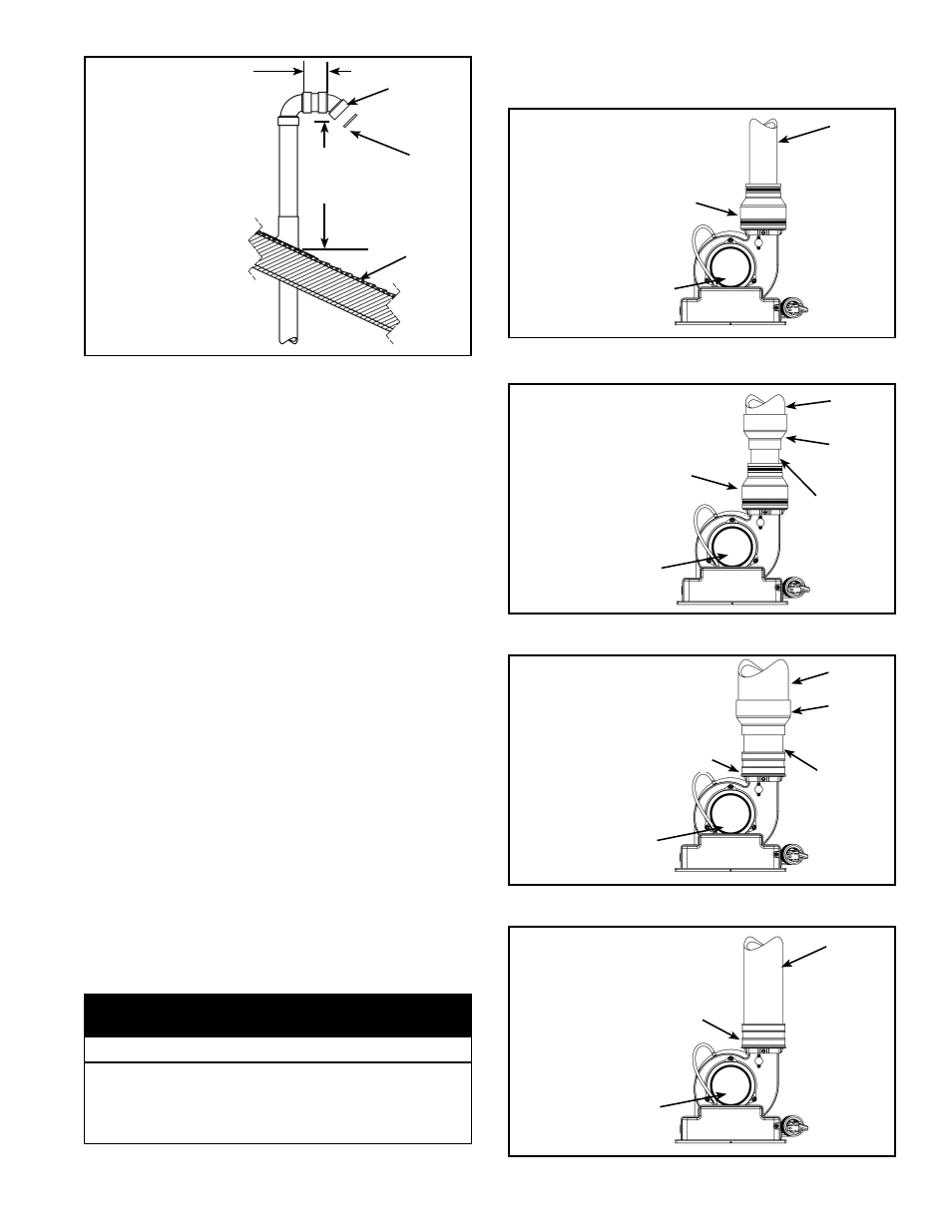
TERMINATION
MAY BE 90°
ELBOW
3” MIN.
LENGTH
ROOF
LINE
A VENT USED IN A
SPECIAL VENTING
SYSTEM WITH POSITIVE
VENT PRESSURE AND
PASSING THROUGH A
ROOF SHALL EXTEND AT
LEAST 18” ABOVE THE
HIGHEST POINT WHERE
IT PASSES THROUGH THE
ROOF SURFACE AND ANY
OTHER OBSTRUCTION
WITHIN A HORIZONTAL
DISTANCE OF 18”. A
VERTICAL VENTING
SYSTEM MUST BE
SUPPORTED EVERY 5 ft..
18” OR
ABOVE
ANTICIPATED
SNOW LEVEL
RODENT
SCREEN
(INSTALL
INTO
ELBOW)
Figure 36.
Vent pipe connection to blower
1. The plastic vent piping connects into the rubber
coupling located on the top of the blower assembly.
This coupling includes gear clamps to connect the
venting to the blower. These connections must be
properly seated and tightened to prevent the leakage
of fl ue gases into the area. See Figure 37 thru Figure
41.
2. The 40, 50 and 60-gallon heaters with rated inputs of
50k Btu/hr or less are designed and supplied with a
2” rubber coupling to accept the vent pipe.
3. The 50 and 75-gallon models with rated inputs of 60k
Btu/hr or more are supplied with a 3” rubber coupling
to accept the vent pipe. Note: Polypropylene vent
systems require separate adaptor.
4. Before installing clean and lightly sand the end of the
PVC/CPVC plastic vent piping that will connect into
the rubber coupling. For polypropylene vent systems
follow manufacturer’s instructions.
5. Loosen the upper clamp on the rubber coupling and
insert the sanded end of the vent piping a full 1-1/4”.
Do not use glue or sealant in the rubber coupling.
Check that there is no stress on the connection or the
vent piping that may be caused by twisting or bending.
6. Tighten the upper clamp so that the vent piping is
fi rmly secured in the coupling and is gas tight. Do not
over tighten or cause distortion of any of the parts.
Ensure the bottom of the rubber coupling is fi rmly
seated on the blower outlet and that the lower gear
clamp is also secure. Check to ensure there is no
distortion or movement of the clamped assembly once
it is completed.
• Do not overtighten the top and bottom gear clamps of the
rubber coupling.
• Do not apply solvent cement or silicone to the rubber
coupling connection.
Property Damage Hazard
CAUTION
Different coupling installations according to vent
sizes
BLOWER
2” VENT
PIPE
2” RUBBER
COUPLING
(SUPPLIED)
CONFIGURATION
FOR 40, 50 AND
60-GALLON (LO-
INPUT) HEATERS
CONNECTED TO
2" VENTING.
Figure 37.
2” RUBBER
COUPLING
(SUPPLIED)
BLOWER
3” VENT
PIPE
2”-3”
ADAPTER*
(FIELD
SUPPLIED)
2” VENT PIPE,
75mm (3 in.)
MAX LENGTH
CONFIGURATION
FOR 40, 50 AND
60-GALLON (LO-
INPUT) HEATERS
CONNECTED TO
3” VENTING.
* FOR 3” DIRECT
CONNECTION TO
THE BLOWER,
ORDER
COUPLING Kit #
9008311005
(SEE ALSO Figure
41).
Figure 38.
4” VENT
PIPE
3” RUBBER
COUPLING
(ORDER COUPLING
Kit # 9008311005
TO REPLACE 2”
RUBBER COUPLING
SUPPLIED.)
3” VENT PIPE,
3 in. MAX
LENGTH
3”-4”
ADAPTER
(FIELD
SUPPLIED)
BLOWER
CONFIGURATION
FOR LO-INPUT
HEATERS
CONNECTED TO
4” VENTING.
LOW-INPUT
HEATERS ARE
SUPPLIED WITH
A 2” RUBBER
COUPLING.
Figure 39.
3” VENT
PIPE
3” RUBBER
COUPLING
(SUPPLIED)
BLOWER
CONFIGURATION
FOR HI-INPUT
HEATERS
CONNECTED TO
3” VENTING.
(OPTIONAL
CONFIGURATION
FOR LO-INPUT
HEATERS
CONNECTED TO
3” VENTING.)
Figure 40.
34 www.statewaterheaters.com