State GS6 75 YRVHTL User Manual
Page 32
Calculating Equivalent Feet
WATER
HEATER
MODEL
HEATER
INPUT
(Btu/hr)
VENT SIZE
(Inside
Diam.)
PRESSURE
SWITCH
SETTING
MAXIMUM EQUIVALENT
VENT LENGTH
MINIMUM EQUIVALENT
VENT LENGTH
40 & 50 gal.
40,000
2”
- 0.27 in. w.c.
50 ft. + termination elbow
7 ft. termination elbow
60 gal.
42,000
- 0.27 in. w.c.
40 & 50 gal.
50,000
- 0.37 in. w.c
40 & 50 gal.
40,000
3”
- 0.27 in. w.c.
125 ft. + termination elbow 7 ft. termination elbow
60 gal.
42,000
- 0.27 in. w.c.
40 & 50 gal.
50,000
- 0.37 in. w.c.
50 gal. (short)
62,000
3”
- 0.99 in. w.c.
50 ft. + termination elbow
7 ft. + termination elbow
50 gal. (tall)
65,000
- 0.99 in. w.c.
75 gal.
72,000
- 0.99 in. w.c.
40 & 50 gal.
40,000
4”
- 0.27 in. w.c.
180 ft. + termination elbow 125 ft. + termination elbow
60 gal.
42,000
- 0.27 in. w.c.
40 & 50 gal.
50,000
- 0.37 in. w.c.
50 gal. (short)
62,000
4”
- 0.99 in. w.c.
125 ft. + termination elbow 50 ft. + termination elbow
50 gal. (tall)
65,000
- 0.99 in. w.c.
75 gal.
72,000
- 0.99 in. w.c.
Equivalent lengths of straight pipe for various elbows using Schedule 40 PVC, CPVC and polypropylene.
Size
Type
Short Sweep/
Short Radius
Long Sweep/
Long Radius
Notes:
1. Use long radius elbows where
possible. Minimum distance between
90º elbows should be 6” wherever
possible.
2. Venting systems may use a maximum
of fi ve (5) 90° elbows.
3. Use proper screen termination (see
Figure 31 & Figure 32).
2”
3"
4"
90° elbow
8 ft.
5 ft.
2”
3"
4"
45° elbow
4 ft.
2.5 ft.
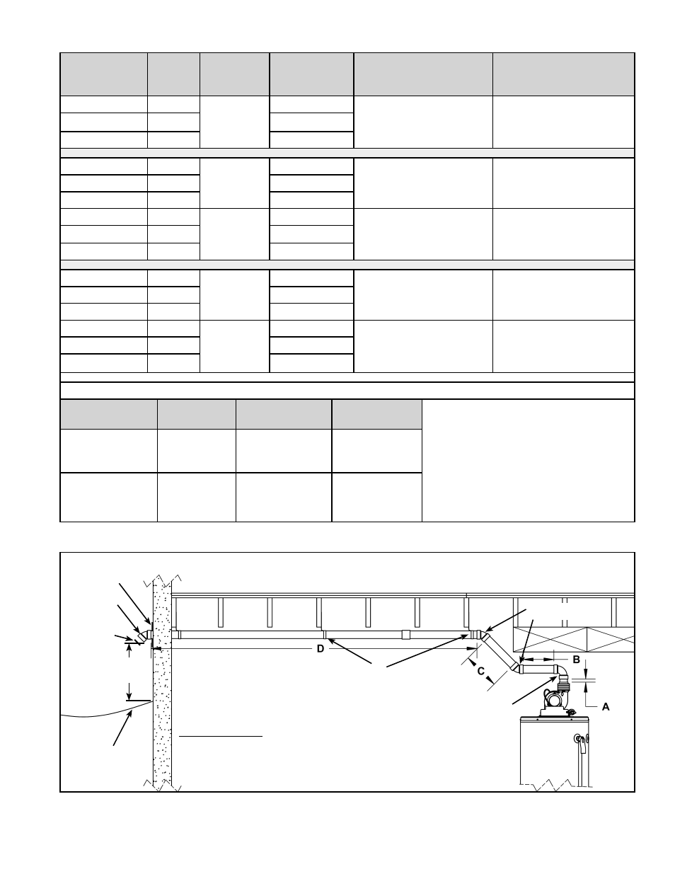
Table 2.
Example for calculating equivalent feet.
Section “A”
0.5 ft.
90° elbow
8.0 ft.
Section B
1.0 ft.
45° elbow
4.0 ft.
Section C
1.5 ft.
45° elbow
4.0 ft.
Section D
15.0 ft.
Total Equivalent 34.0 ft.
Based on this example use the (fully open) rodent
screen for vent length greater than 20 equivalent ft.
(see Figure 31 & Figure 32).
Note: The vent pipe must be supported every 4 ft.. To prevent vibration and sagging, it is recommended to use
isolation pads when attaching straps to fl oor joists, walls or ceilings. PVC and CPVC vent pipe should be sloped
upwards away from the blower assembly at a pitch of 1/8 in. rise per 4 ft.. Polypropylene vent systems require a
1/4” per 1 ft. upward slope to ensure proper drainage.
STRAP
45° SHORT
ELBOW
90° SHORT
ELBOW
RODENT
SCREEN
(INSTALL INTO
ELBOW)
TERMINATION
ELBOW
GROUND LEVEL
12” MIN. OR ABOVE
ANTICIPATED SNOW
LEVEL.
COVER PLATE
(OPTIONAL)
Figure 33.
32 www.statewaterheaters.com