Checking error code chart – GReddy TURBO KITS: Honda Civic Si 2002-05 / T517Z User Manual
Page 23
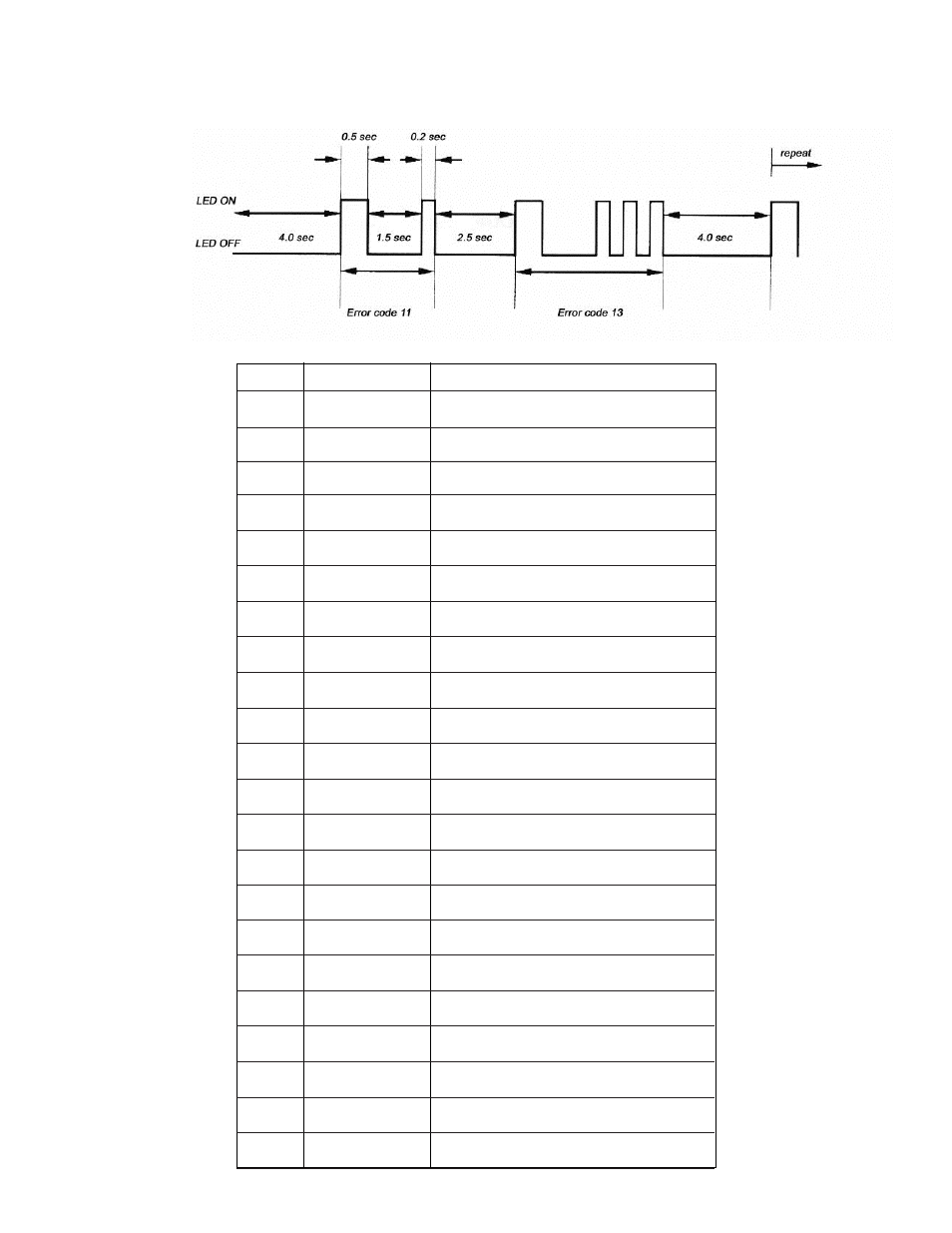
Checking Error Code Chart
CODE
Incorrect wiring or disconnected Airflow Signal 1
input error
11
15
Airflow Signal 1
No Injec
Airflow voltage
pulse from all
tor 1 pulse
No Injector 2 pulse
e
Incorrect Airflow signal output wiring.
signal for
Additional Injection Map
Not receiving injector signal I/J CH-1
Not receiving injector signal I/J CH-2
for Additional Injection Map
Not receiving injector signal I/J CH-3
for Additional Injection Map
20
22
40
41
42
43
44
51
52
53
54
57
Improper order of
Ignition input signal
Error
Error description
Incorrect wiring order of the ignition signal wires.
No Ignition Signal 1
pulse
No Ignition Signal 2
pulse
No Ignition Signal 3
pulse
No Ignition Signal 4
pulse
Not receiving the ignition signal to IG CH-1
Not receiving the ignition signal to IG CH-2
Not receiving the ignition signal to IG CH-3
Not receiving the ignition signal to IG CH-4
pulse
Incorrect Ignition 2
pulse
Incorrect Ignition 3
pulse
Incorrect Ignition 4
pulse
JP2 + 12V
error
Incorrect IG CH-1 wire to e-Manage unit
Incorrect IG CH-2 wire to e-Manage unit
Incorrect IG CH-3 wire to e-Manage unit
Incorrect IG CH-4 wire to e-Manage unit
Incorrect Jumper setting (JP2)
Not receiving the ignition signal
y of the channels
output error
No Injector
Not receiving an injector
for Additional Injection Map
21
No Injector 3 puls
23
No Injector 4 pulse
Not receiving injector signal I/J CH-4
for Additional Injection Map
24
31
32
33
34
Incorrect Injector 1
pulse
Incorrect Injector 2
pulse
Incorrect Injector 3
pulse
Incorrect Injector 4
pulse
Incorrect I/J CH-1 wire to e-Manage unit
Incorrect I/J CH-2 wire to e-Manage unit
Incorrect I/J CH-3 wire to e-Manage unit
Incorrect I/J CH-4 wire to e-Manage unit
49
Incorrect Ignition 1
No Ignition pulse
to an