Electrical connections, Montaje del tacometro, Green wire connection – Actron CP7906 User Manual
Page 3: Seleccion de cilindros, Sustitucion o reemplazo de la lampara, Indicador de linea roja / cambio de marcha, Prueba funcional rapida
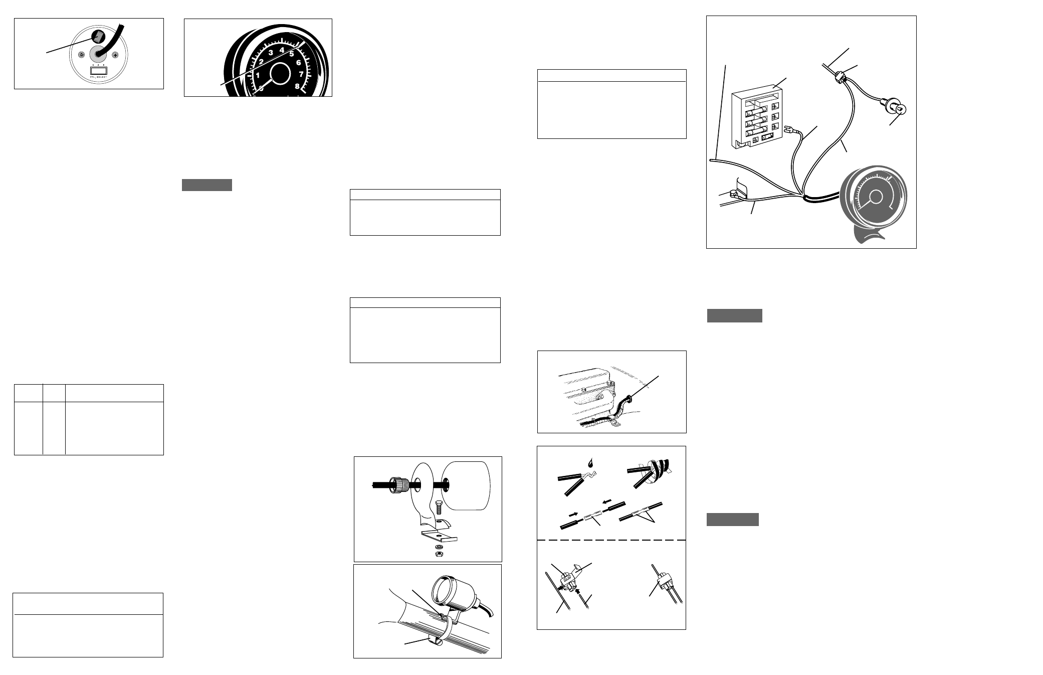
FIGURE 5
RUBBER
GROMMET
FIGURE 6
SOLDER
CONNECTOR
VEHICLE
HARNESS WIRE
PIERCING
CLIP
CONNECTOR
LIP
UNLOCKED
TACHOMETER
WIRE
SPLICE
CONNECTOR
LOCKED
ELECTRICAL
TAPE
CRIMP ENDS
ELECTRICAL
CONNECTIONS
Refer to your vehicle service manual while
carefully following the wiring instructions.
CAUTION
For your own personal safety, and to
prevent possible damage to the
electrical system of your vehicle
during the installation, disconnect the
negative (-) battery cable. Reconnect
this cable after installation is complete.
BLACK, RED, AND WHITE
WIRE CONNECTIONS –
ALL SYSTEMS
Route all wires carefully. Securing them with
nylon tie wraps (not included) is suggested.
Do not route wires along or against sharp
edges which could cut the insulation. Also,
do not route them along hot engine sur-
faces, such as exhaust manifolds, where
high temperature could melt the insulation,
or near spark plug wires.
Route wires through an existing hole in the
firewall, or drill a 3/8" hole where desired,
making sure there are no hidden wires,
hoses, etc. that could be damaged. Insert
the supplied rubber grommet in this hole for
added protection against wire damage or
shorting (see figure 5).
0
1
2
3 4 5
6
7
8
Sun super tach
RPM x 1000
FIGURE 7
BLACK WIRE
TO GROUND
SEE THE GREEN WIRE
CONNECTION SECTIONS
OF THIS MANUAL
FUSE
BOX
RED TO
BATT.
VOLTAGE
TERMINAL
INSTRUMENT
LAMP
SPLICE
CONNECTOR
TO
DIMMER
SWITCH
1. Connect the BLACK wire to the negative
(-) battery terminal, or a clean unpainted
chassis ground using a ring terminal or
other suitable means (see figure 7).
IMPORTANT
Although electrical ground (BLACK wire
connection) is available under the dash-
board, grounding the instrument near or
under the dash may cause it to operate
erratically, as any ground connection other
than the negative (-) battery terminal may
be “electrically noisy”.
Make the following connections with splice
connectors, or by an alternative method if
desired (see figure 6).
2. Connect the RED wire to any vehicle
harness wire which is energized with
battery voltage ONLY when the ignition key
is in the ON (RUN) position, NOT OFF or
ACCESSORIES (see figures 6 and 7).
3. Connect the WHITE wire to the instru-
ment panel lighting circuit or any lead that
is controlled by the instrument panel
dimmer control (see figure 7).
NOTE
Some vehicles (typically imported) wire the
dimmer control into the ground side of the
instrument panel lighting circuit, as opposed
to the more conventional “hot” or twelve (12)
volt side. In vehicles which use this circuit,
connect the WHITE wire to a circuit which is
energized by the headlamp switch.
GREEN WIRE
CONNECTION
The GREEN wire provides
the tachometer with the
engine RPM (speed) signal.
If your vehicle's engine is
equipped with a DISTRIBU-
TOR IGNITION SYSTEM
proceed to the GREEN
WIRE CONNECTION -
DISTRIBUTOR EQUIPPED
ENGINES section in this
manual. If your vehicle’s
engine is equipped with a
DIS (DISTRIBUTORLESS
IGNITION SYSTEM)
proceed to the GREEN
WIRE CONNECTION -
DISTRIBUTORLESS
IGNITION SYSTEM
EQUIPPED ENGINES
section of this manual. DIS
equipped engines are
characterized by their lack of
an ignition distributor. In
place of the distributor, will
be one or more “ignition coil
packs”. Unlike the ignition
distributor which has a basically round
shape, the coil pack is typically a square or
rectangular package.
GREEN WIRE CONNECTION
DISTRIBUTOR EQUIPPED
ENGINES
Connect the GREEN wire to the negative (-)
side of the ignition coil. This terminal may
also be referred to as the TACH, TACH
TEST, DEC, or ECU terminal. Wiring
diagrams can be found in your vehicle
service manual. See the list at the end of
these instructions for service manual
sources.
GREEN WIRE CONNECTION
DISTRIBUTORLESS IGNITION
SYSTEM EQUIPPED ENGINES
Many domestically built vehicles (and some
imports) are now using a new type of ignition
system which does not use a distributor, but
instead, a system of multiple ignition coils, and
the necessary sensors and computer
controls to fire them in the proper order.
This type of system is commonly referred to
as a DISTRIBUTORLESS IGNITION
SYSTEM or DIS. Your tachometer is
designed to work with these systems,
however proper connection to them is
important. The BLACK (ground), RED (12-
14 volt supply), and WHITE (instrument
lamp) connections are the same as for
distributor equipped vehicles, however
connection of the GREEN (tach signal) wire
to the ignition is specific to the engine and
ignition system. Wiring diagrams can be
found in your vehicle service manual. See
the list at the end of these instructions
for service manual sources.
3
WHITE
SELECCION DE CILINDROS
Antes de su instalación, se debe verificar la
configuración de cilindros en el tacómetro (vea
la figura 1). Posicione la llave selectora de
cilindros (CYL) ubicada en la parte posterior
del tacómetro de modo tal que el actuador de la
llave quede en posición opuesta al número que
coincida con el número de cilindros del motor.
CONEXIONES DEL SISTEMA DE
ENCENDIDO SIN DISTRIBUIDOR, DE
CHRYSLER: la conexión a la terminal (Pin)
43 del Controlador de Motor de Placa de
Circuito Unica (Single Board Engine
Controller) en los vehículos Chrysler
equipados con Sistema de Encendido sin
Distribuidor, requiere que la llave selectora
CYL quede en la posición de cuatro (4)
cilindros, independientemente del número de
cilindros del motor.
SUSTITUCION O REEMPLAZO
DE LA LAMPARA
Su tacómetro está provisto, para su iluminación,
de una lámpara del tipo usado en automóviles,
de base en cuña (tacómetros de tamaño
normal) o de base en cuña subminiatura (mini
tacómetros). La lámpara debe proveer una
intensidad de iluminación satisfactoria en la
mayoría de las aplicaciones. Sin embargo, en
su tienda local de autopiezas están disponibles
las lámparas de sustitución que se indican a
continuación, y que le posibilitarán adaptar las
características de iluminación del tacómetro a
su aplicación particular. Tenga en cuenta que
cuanto mayor sea el número de MSCD
(Intensidad luminosa en Candela Esférica
Promedio), más brillante es la lámpara.
Nº DE
MSCD
COLOR
BASE
LAMPARA
73,3
TRANSPARENTE CUÑA SUBMINIATURA
3
7
,5 TRANSPARENTE CUÑA SUBMINIATURA
74
,75 TRANSPARENTE CUÑA SUBMINIATURA
161
1
TRANSPARENTE
CUÑA
194
2
TRANSPARENTE
CUÑA
194A
-
RECUBRIMIENTO
AMBAR
CUÑA
168
3
TRANSPARENTE
CUÑA
El socket de la lámpara está ubicado en el tope
de la cara posterior del tacómetro (vea la figura
1). Para retirar la lámpara, tome suavemente el
socket negro de la lámpara (use pinzas, si fuera
necesario) y hágalo girar en sentido contrario a la
manecillas del reloj aproximadamente 1/8 de
vuelta, hasta que haga tope. Tire del socket con
la lámpara en forma recta hacia afuera del
alojamiento del tacómetro. Extraiga la lámpara de
su socket tirando de ella en forma recta hacia
afuera. Reemplace la lámpara según sus
necesidades, de acuerdo con el cuadro de más
arriba. Reinstale la lámpara ya colocada en el
socket, haciéndola girar contra la placa de
circuito impreso del tacómetro hasta que encaje
en su lugar, y luego hágala girar
aproximadamente 1/8 de vuelta en sentido
horario, hasta que alcance su tope mecánico.
ADVERTENCIA-¡PRECAUCION DE
SEGURIDAD!
¡Ni el conductor ni ninguno de los
pasajeros debe comprometer la operación
segura del vehículo intentando reajustar el
tacómetro, de ninguna manera, mientras el
vehículo esté en movimiento!
ignición o de la bobina de ignición para
obtener información relativa a la conexión
del tacómetro a su producto y/o la
disponibilidad de un conjunto de filtro
eléctrico, si fuera necesario.
Una vez que usted esté satisfecho con el
desempeño del tacómetro, siga adelante con
las instrucciones para la instalación
permanente que se indican a continuación.
MONTAJE DEL
TACOMETRO
Su tacómetro está diseñado para montarse
encima o debajo del tablero, o en la columna de
dirección (vea las figuras 3 y 4). Si usted elige
la configuración de montaje en la columna de
dirección, se necesitará obtener una
abrazadera para manguera con un diámetro
que sea lo suficientemente grande como para
rodear la columna de dirección. Una vez que el
montaje de la abrazadera se haya completado,
corte el el sobrante de la tira de la misma.
ATENCION
Algunas columnas de dirección están
construídas de modo de plegarse en caso de
impacto. Al ajustar la abrazadera, hágalo con
cuidado para evitar dañar la columna.
Asegúrese de no interferir con el movimiento
o el mecanismo de las columnas de dirección
ajustables/inclinables.
Seleccione una ubicación de montaje que
permita una visión despejada del tacómetro,
pero que no obstruya el acceso o la visión de
los controles, o la visión de otros
instrumentos del tablero, o del camino.
ATENCION
¡Posicione el tacómetro en su ubicación
específica y determine el encaminamiento de
los cables y las ubicaciones de conexión
antes de perforar ningún agujero! ¡Asegúrese
de inspeccionar detrás de los lugares donde
piensa hacer perforaciones para ver si hay
obstrucciones, antes de proceder a perforar!
Marque las ubicaciones de los agujeros, y
perfore los agujeros según los requisitos del
cuadro siguiente.
Tornillos autorroscantes Nº 8:Broca No 29 o
9/64" EUA (0,356cm)
Tornillería con tornillos para metal Nº 8:
Broca No 18 o 11/64 EUA (0,435cm)
Agujero de paso para el manojo de cables:
Broca de 3/8" EUA (9,52 cm)
Una vez que el tacómetro esté ajustado en su
posición final, apriete firmemente toda la
tornillería.
FIGURA 2
FIGURA 3
FIGURA 4
ABRAZADERA
DE MANGUERA
INDICADOR
DE LINEA
ROJA /
CAMBIO
DE
MARCHA
ALMOHADILLA
DE GOMA
10
INDICADOR DE LINEA ROJA /
CAMBIO DE MARCHA
Ajuste el INDICADOR DE LINEA ROJA /
CAMBIO DE MARCHA deslizándolo
alrededor del marco del medidor (vea la
figura 2). Este indicador puede ajustarse en
cualquier punto de la escala del medidor, tal
como la línea roja del motor, o un punto de
cambio de marcha de la transmisión.
NOTA
PRUEBA FUNCIONAL RAPIDA
Si bien se han hecho todos los intentos para
hacer que este tacómetro sea
electrónicamente compatible con tantos
sistemas diferentes de encendido como sea
posible, continuamente se están
desarrollando sistemas de encendido nuevos.
Se sugiere (especialmente si su motor tiene
un sistema de encendido no incorporado al
vehículo en fábrica [Original Equipment
Manufacturer - OEM] sino adquirido en el
mercado de posventa), conectar
eléctricamente el tacómetro al vehículo (por
medio de cables provistos de clips cocodrilo
u otros medios adecuados) siguiendo los
pasos que se detallan a continuación, y llevar
a cabo de seguros tipo cocodrilo una prueba
funcional eléctrica del tacómetro antes de
proceder a su instalación permanente.
1. Sujete el cable NEGRO del tacómetro
al terminal negativo (-) de la batería.
2. Sujete el cable ROJO del tacómetro al
terminal positivo (+) de la batería.
3. Sujete el cable VERDE del tacómetro al
lado negativo (-) de la bobina de
encendido o al punto de conexión de la
señal de tacómetro, como se indica en
la sección CONEXIONES ELECTRICAS
de este manual. ¡No permita que esta
conexión haga contacto con tierra!
4. El cable BLANCO es para iluminación
del panel de instrumentos, y no necesita
conectarse para esta verificación.
5. Cuando todas las conexiones estén
seguras, haga arrancar el motor del
vehículo. Confirme la operación del
tacómetro a través de la gama de
temperaturas de operación del motor, y
tanto en condiciones de marcha en vacío
(ralentí) como a velocidades de motor
mayores. El tacómetro debe seguir la
velocidad del motor en forma gradual,
sin mostrar signos de operación errática.
Si usted encontrara que la operación del
tacómetro no es satisfactoria (funcionamiento
errático, falta de indicación, etc.) en motores
equipados con sistemas de encendido o
bobinas de encendido de alto desempeño y/o
adquiridos en el mercado de posventa,
puede ser que usted haya seleccionado un
punto incorrecto de conexión de la señal de
tacómetro para el cable VERDE del
tacómetro, o que sea necesario incluír un
conjunto de filtro para el tacómetro.
Contacte con el fabricante del sistema de
FIGURA 1
SOCKET
DE LA
LAMPARA