Mounting the tachometer, Conexiones electricas, Cylinder selection – Actron CP7906 User Manual
Page 2: Lamp substitution or replacement, Red line / shift pointer, Functional quick check, Conexion del cable verde
CYLINDER SELECTION
This tachometer should be checked for cylinder
setting before installation (see figure 1).
Position the CYLinder selector switch on the
rear of the tachometer so that the switch
actuator is opposite the number which matches
the number of cylinders in the engine.
For Chrysler DISTRIBUTORLESS IGNI-
TION SYSTEM CONNECTIONS, connection
to Pin 43 of the Single Board Engine
Controller on Distributorless Ignition equipped
Chrysler vehicles requires that the CYLinder
selector switch be set to the four (4) cylinder
position, regardless of the number of
cylinders in the engine.
LAMP SUBSTITUTION OR
REPLACEMENT
Your tachometer is supplied with an automo-
tive type, wedge base (full size tachometers)
or subminiature wedge base (mini tachom-
eters) lamp, for illumination. This lamp should
provide satisfactory illumination intensity in
most applications, however the following
substitute lamps are available at your local
auto parts store, and may allow you to
custom tailor the illumination characteristics
of the tachometer to your application. Note
the higher the MSCD (Mean Spherical
Candela) of the lamp, the brighter it is.
LAMP #
MSCD
COLOR
BASE
73.3 CLEAR
SUBMINIATURE WEDGE
37
.5
CLEAR
SUBMINIATURE WEDGE
74
.75
CLEAR
SUBMINIATURE WEDGE
161
1
CLEAR
WEDGE
194
2
CLEAR
WEDGE
194A
-
AMBER COATED
WEDGE
168
3CLEAR
WEDGE
The lamp socket is located at the top rear of
the tachometer (see figure 1). To remove the
lamp, gently grasp the black lamp socket (use
pliers if necessary) and twist it counter-
clockwise approximately 1/8 turn until it stops.
Pull the socket with lamp straight out of the
tachometer housing. Remove the lamp from
its socket by pulling it straight out. Replace
the lamp as required following the chart
above. Reinstall the socketed lamp by rotating
it against the tachometers PC board until it
drops into place, and then rotate it approxi-
mately 1/8 turn clockwise until it reaches its
mechanical stop.
WARNING - SAFETY PRECAUTION!
Neither the driver nor any passenger
should compromise the safe operation
of the vehicle by attempting to readjust
the tachometer in any way while the
vehicle is in motion!
MOUNTING THE
TACHOMETER
Your tachometer is designed to be mounted
on top of or underneath the dashboard, or on
the steering column (see figures 3 and 4). If
you choose the steering column mounting
configuration, it will be necessary to obtain a
hose clamp which is large enough in
diameter to encircle the steering column. Cut
off any excess strap from the hose clamp,
when clamp mounting is complete.
CAUTION
Some steering columns are made to be
collapsible upon impact. Care should be
taken when tightening the clamp to
avoid damage to the column.
Be sure not to interfere with the movement
or mechanism of adjustable/tilt steering
columns.
Select a mounting location that allows a clear
view of the tachometer, but does not
obstruct access or view of controls, or view
of other dashboard instruments, or the road.
CAUTION
Position the tachometer in its specific
location and determine wire routing and
connection locations before drilling any
holes! Be sure to check behind areas of
intended drilling for obstructions before
drilling!
Mark hole locations, and drill holes as
required per the following chart.
# 8 Self-tapping screws #29 or 9/64" drill bit
# 8 Machine screw hardware #18 or 11/64" drill bit
Clearance hole for wiring harness 5/16" drill bit
Once the tachometer is adjusted to its final
position, securely tighten all hardware.
FIGURE 2
FIGURE 3
FIGURE 4
HOSE CLAMP
RED LINE/
SHIFT
POINTER
RUBBER
PAD
2
RED LINE / SHIFT POINTER
Adjust the RED LINE/SHIFT POINTER by
sliding it around the meter bezel (see figure
2). This pointer may be set at any point on the
meter scale, such as engine red line, or
transmission shift point.
NOTE
FUNCTIONAL QUICK CHECK
Although every attempt has been made to
make this tachometer electronically compatible
with as many different ignition systems as
possible, new ignition systems are being
developed continually. It is suggested
(especially if you have an engine that has a
non OEM, or aftermarket ignition system) that
the tachometer be electrically connected to
the vehicle, (using alligator clip leads or other
suitable means) following the steps below,
and an electrical functional check of the
tachometer be made, prior to making a
permanent installation.
1. Clip the BLACK lead from the tachometer
to the negative (-) battery terminal.
2. Clip the RED lead from the tachometer to
the positive (+) battery terminal.
3. Clip the GREEN lead from the tachometer
to the negative (-) side of the ignition coil
or tach signal connection point as indi-
cated in the ELECTRICAL CONNEC-
TIONS section of this manual. Do not
allow this connection to touch ground!
4. The WHITE lead is for instrument panel lighting,
and need not be connected for this check.
5. When all connections are secure, start the
vehicles engine. Confirm the operation of
the tachometer throughout the operating
temperature range of the engine, and at
both curb idle, and higher engine speeds.
The tachometer should follow the speed of
the engine smoothly, and show no signs of
erratic operation.
Should you encounter unsatisfactory tachom-
eter operation (erratic, no reading, etc.) on
engines equipped with high performance and/
or aftermarket ignition systems or ignition coils,
you may have selected the incorrect tach
connection point for the tachometers GREEN
lead, or a tachometer filter assembly may be
required.
Contact the manufacturer of the ignition
system or ignition coil for information
regarding tachometer connection to his
product and/or the availability of an
electrical filter assembly if required.
When you are satisfied with tachometer
performance, proceed to the permanent
installation instructions which follow.
FIGURE 1
LAMP
SOCKET
FIGURA 5
ARANDELA
DE GOMA
FIGURA 6
SOLDADOR
CONECTOR
CABLE, HARNES
DEL CABLEADO
DEL VEHICULO
GRAPA
PERFORADORA
BORDE DEL
CONECTOR,
SIN TRABA
CABLE DEL
TACOMETRO
CONECTOR
DE
EMPALME,
TRABADO
CINTA AISLANTE
ELECTRICA
ENGASTAR
EXTREMOS
CONEXIONES
ELECTRICAS
Consulte el manual de servicio de su vehículo
mientras sigue cuidadosamente las
instrucciones del cableado.
ATENCION
Para su propia seguridad personal, y para
impedir posibles daños al sistema
eléctrico de su vehículo durante la
instalación, desconecte el cable negativo
(-) de la batería. Reconecte este cable
después de haber completado la
instalación.
CONEXIONES DE LOS
CABLES NEGRO, ROJO Y
BLANCO, PARA TODOS LOS
SISTEMAS
Encamine todos los cables cuidadosamente.
Se sugiere asegurarlos con lazos de
sujeción de nylon (no se incluyen). No
encamine los cables a lo largo de o contra
bordes filosos, que podrían cortar el aislante.
Además, no los encamine a lo largo de
superficies calientes del motor, tales como
múltiples de escape, , donde la alta
temperatura podría fundir el aislante, o cerca
de los cable de bujía.
Encamine los cables a través de un agujero
existente en la mampara cortafuegos, o
perfore un agujero de 3/8" EUA (0,952 cm)
donde desee, asegurándose de que no haya
lámpara, mangueras, etc., ocultos que
pudieran dañarse. Para asegurar una mayor
protección contra daños en los cables o
cortocircuitos, inserte en este agujero la
arandela de goma provista (vea la figura 5).
0
1
2
3 4 5
6
7
8
Sun super tach
RPM x 1000
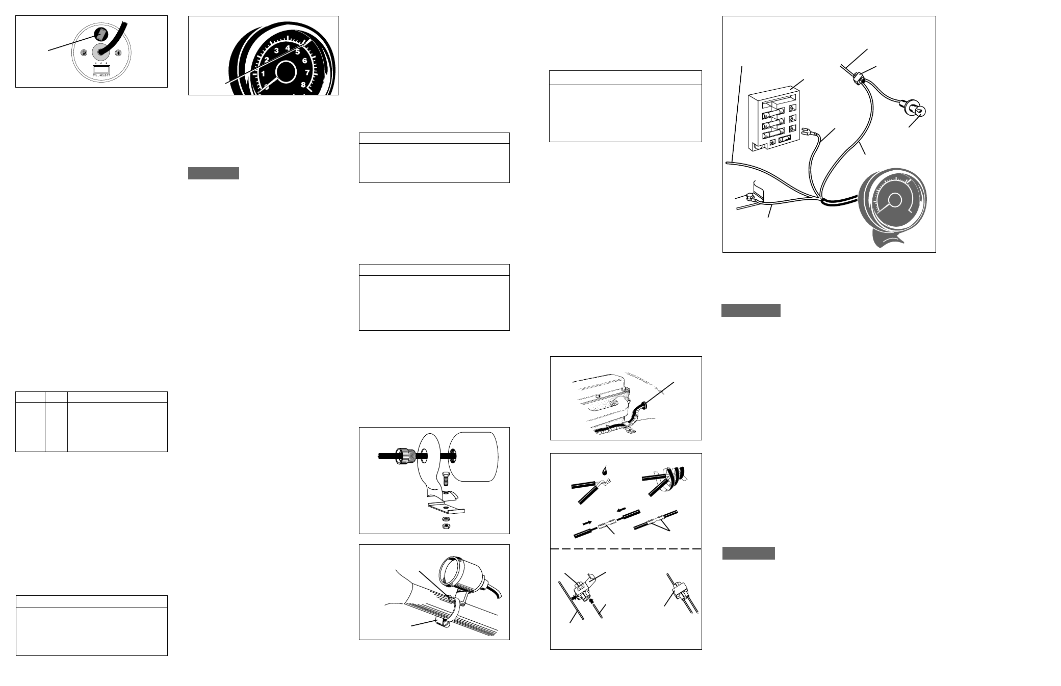
FIGURA 7
CABLE NEGRO,
A TIERRA
VEA LA SECCION
CONEXION DEL CABLE
VERDE DE ESTE MANUAL
CAJA DE
FUSIBLES
ROJO AL
TERMINAL DE
TENSION DE
BATERIA
LAMPARA
PARA
INSTRUMENTOS
CONECTOR
DE EMPALME
1. Conecte el cable NEGRO a la terminal
negativa (-) de la batería, o a un punto de
tierra del chasis que esté limpio y sin
pintura, usando un terminal tipo anillo u
otro medio adecuado (vea la figura 7).
IMPORTANTE
Si bien existe una conexión eléctrica de
tierra (conexión del cable NEGRO)
disponible bajo el tablero, la puesta a tierra
del instrumento cerca del tablero o debajo
de él puede originar una operación errática,
debido a que toda conexión de tierra que
sea distinta de la terminal negativa (-) de la
batería puede ser eléctricamente ruidosa.
Haga las conexiones que siguen mediante
conectores de empalme, o por algún medio
alternativo si así lo desea (vea la figura 6).
2. Conecte el cable ROJO a cualquier cable
del manojo de cables del vehículo que
esté energizado con la tensión de batería
UNICAMENTE cuando la llave de
encendido se encuentre en la posición
MARCHA (ON o RUN), y NO cuando
esté en las posiciones APAGADO (OFF)
o ACCESORIOS (ACCESORIES) (vea
las figuras 6 y 7).
3. Conecte el cable BLANCO al circuito de
iluminación del panel de instrumentos, o a
cualquier punto de conexión eléctrica que
esté controlado por el control del
atenuador de luz (dimmer) del panel de
instrumentos (vea la figura 7).
NOTA
Algunos vehículos (generalmente fabricados
fuera de EUA) conectan el control del
atenuador de luz (dimmer) en el lado de
tierra del circuito de iluminación del panel de
instrumentos, contrariamente al modo más
convencional de conectarlo en el lado
positivo (tensión +12V). En vehículos que
usen este circuito, conecte el cable BLANCO
a un circuito que esté energizado por el
interruptor de los faros delanteros.
CONEXION DEL
CABLE VERDE
El cable VERDE entrega al
tacómetro la señal que
representa la velocidad del
motor en número de
revoluciones por minuto (r/
min). Si el motor de su
vehículo está equipado con un
SISTEMA DE ENCENDIDO
CON DISTRIBUIDOR, vaya a
la sección de este manual
titulada CONEXIÓN DEL
CABLE VERDE MOTORES
EQUIPADOS CON
DISTRIBUIDOR Si el motor
de su vehículo está equipado
con un SISTEMA DE
ENCENDIDO SIN
DISTRIBUIDOR (DIS) vaya
a la sección de este manual
titulada CONEXIÓN DEL
CABLE VERDE
MOTORES EQUIPADOS
CON SISTEMAS DE
ENCENDIDO SIN
DISTRIBUIDOR. Los
motores equipados con DIS
se caracterizan por la
ausencia de un distribuidor
de encendido. En lugar del distribuidor, habrá
uno o más conjuntos de bobina de
encendido. A diferencia del distribuidor de
encendido, que tiene una forma básicamente
redonda, el conjunto de bobina tiene
generalmente un empaque de forma
cuadrada o rectangular.
CONEXIÓN DEL CABLE VERDE
MOTORES EQUIPADOS CON
DISTRIBUIDOR
Conecte el cable VERDE al lado negativo (-)
de la bobina de encendido. Esta terminal
puede tener también la denominación TACH,
TACH TEST, DEC o ECU. En el manual de
servicio de su vehículo podrá encontrar
diagramas de conexión. Vea la lista de las
fuentes de manuales de servicio, al final
de estas instrucciones.
CONEXIÓN DEL CABLE VERDE
MOTORES EQUIPADOS CON
SISTEMAS DE ENCENDIDO SIN
DISTRIBUIDOR
Muchos vehículos construídos en los Estados
Unidos de América (y algunos de otros
países) están usando hoy en día un nuevo
tipo de sistema de encendido que no usa
distribuidor sino que lo reemplaza por un
sistema de bobinas de encendido múltiples,
con los sensores y controles computarizados
necesarios para activarlas en el orden
correcto. A este tipo de sistema se le
denomina comúnmente SISTEMA DE
ENCENDIDO SIN DISTRIBUIDOR, o por
medio de sus iniciales en inglés DIS. Su
tacómetro está diseñado para trabajar con
estos sistemas, pero es importante
conectarlos correctamente. Las conexiones
de los cables NEGRO (tierra), (alimentación
eléctrica de tensión 12V a 14V) y BLANCO
(lámpara para instrumentos) son iguales que
en los vehículos equipados con distribuidor,
pero la conexión del cable VERDE (señal de
tacómetro) al sistema de encendido es
específica del motor y del sistema de
encendido mismo. Los diagramas de
conexionado se pueden encontrar en el
manual de servicio de su vehículo. Vea las
fuentes de manuales de servicio en la lista
que está al final de estas instrucciones.
11
BLANCO
AL INTERRUPTOR DEL
ATENUADOR DE LUZ (DIMMER)