Actron CP7005 User Manual
Dépannage, Installation, Precautions
10. Never install the captive fitting on the capillary
tube directly into the engine without an adapter,
as a proper seal will not be formed.
INSTALLATION
Note: If you are planning to use both an oil temperature
gauge and an oil pressure gauge, some modifications
may be necessary as there is only one available hole for
both senders. Since the temperature gauge cannot use
a T-fitting, we suggest that you install the oil temperature
sender into the oil pressure warning light sender location
in the engine block. Then obtain an adapter (which we do
not manufacture) used for oil coolers which will give you
an additional outlet for oil pressure.
Gauge Installation
Make temporary test connection before permanently
mounting hardware or drilling holes.
This gauge can be mounted into any surface or
into a gauge pod. Refer to Figure 1.
Temperature gauges measure the temperature
of any liquid their sender tip is submerged in. An
electrical temperature gauge is simpler and more
versatile for installation than a mechanical gauge,
but is not quite as fast to respond to temperature
changes.
A temperature gauge requires that its sender tip
have a circulating flow around it to give an accu-
rate reading. For this reason, a T-fitting cannot be
used because it has no circulation therefore the
original warning light sender cannot be operated
off the same location. An additional location may
be available on the cylinder head, intake manifold,
or thermostat housing, but caution should be used
in that these locations may have different aver-
age temperatures than the original warning light
sender location.
NOTE: Some vehicles use electric cooling fans or micro-
processor engine controls that depend on readings from
the original equipment sending units for correct operation.
If your vehicle is one of these, then you CANNOT change
the OEM (original equipment manufacturer) sending
units(s). The only possible way to use non OEM sender
is to install it in a different location and leave the OEM
sender in its original location. Check with the vehicle’s
manufacturer or dealer to see if this is possible.
PRECAUTIONS
1. Disconnect the battery ground cable before
performing any electrical work.
2 Route all wiring away from linkages, engine
parts that become hot, or moving parts.
3. Never smoke while working on your vehicle
and always keep a fire extinguisher nearby.
It should be rated for gas/chemical/electrical
fires.
4. Never lay tools on top of the battery or wear
jewelry during electrical work to avoid severe
electrical shorts.
5. Locate and operate gauges so that driving
visibility is not compromised.
6. Do not overtighten the fittings or sender,
particularly for mechanical gauges. The
threads are designed to strip before the engine
component can be damaged. The fittings use
tapered self-sealing threads and do not require
extreme force to seal properly.
7. Do not use sealing tapes or compounds on
electrical senders as this will disturb their
grounding connection to the engine resulting
in false low readings.
8. Take caution when uncoiling and routing the
mechanical gauge’s capillary tubing so that you
do not bend it too sharply or flex it too often. Any
break in the inner tube will make the gauge non-
repairable. A replacement service is available
only at the factory service center.
9. Always install the adapter fitting into the engine
first and then tighten the captive fitting (Figure 3)
on the capillary tube to avoid twisting the tubing.
WATER/OIL AND TRANSMISSION
FLUID TEMPERATURE GAUGES
INSTALLATION INSTRUCTIONS
gAuge
DAshboARD
bRAckeT
NuTs
(kNuRLeD)
Figure 1
Gauge Mounting:
Do not install bracket and nuts until reaching step 6
in the For Mechanical Gauges section or step 10 in
For Electrical Gauges section.
1. Disconnect the battery ground cable before
performing any electrical work.
2. choose a location to mount the gauge where
it will be viewable from a normal driving
position.
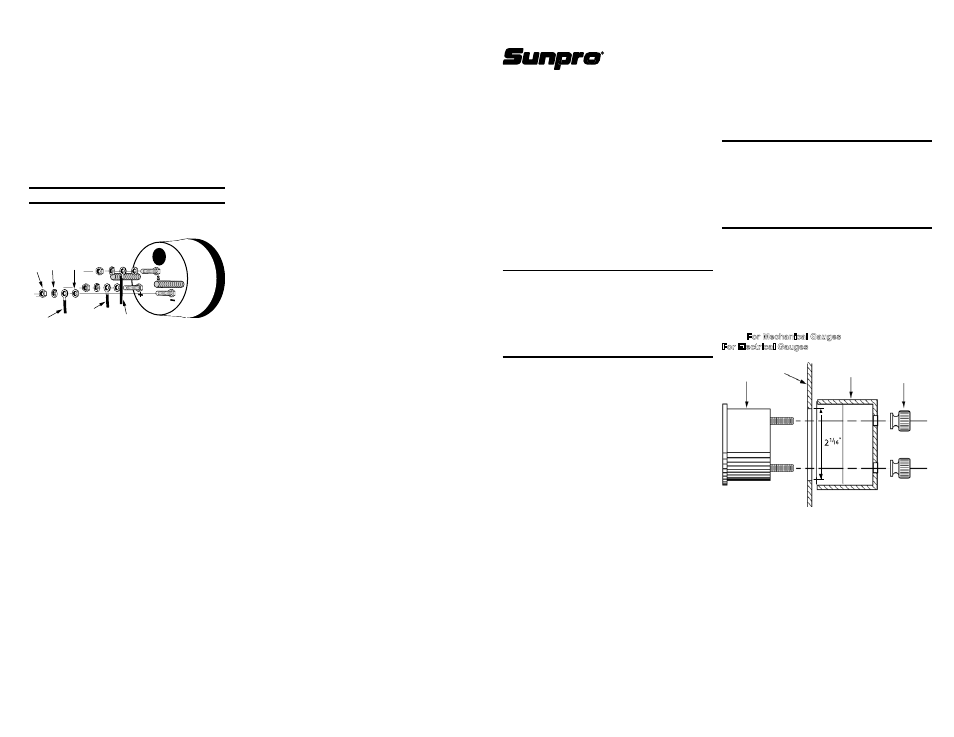
3. If you are installing the gauge into a surface (for
example the dashboard) make a 2-1/16” hole
for the gauge. Do not accidentally cut any wires
or hoses. be sure there is clearance around the
hole for the gauge mounting bracket.
sunpro
®
15825 Industrial Parkway,
cleveland, oh 44135, u.s.A.
©2006 sPX corporation
sunpro
®
is a registered trademark of snap-on
®
corporation used under license to
sPX
®
corporation
0002-000-2908
For warranty information
contact us at:
1-800 228-7667 or www.sunpro.com
6. Après que vous ayez monté la mesure, reliez
le fil d’expéditeur au poteau de raccordement
de “s” comme représenté sur le schéma 4.
L’excédent ne serrent pas.
7. connectez une extrémité d’une autre longueur
de fil de calibre 18 en cuivre isolé sur la
borne “–”, comme illustré au schéma 4, et son
autre extrémité sur un point de bonne masse
électrique.
8. connectez une troisième longueur de fil de
calibre 18 en cuivre isolé sur la borne “+”,
comme illustré au schéma 4, et son autre
extrémité sur une borne de la boîte de fusibles
(12V) qui reste alimentée en tension que la clé
de contact soit dans n’importe quelle position
(sTART, oN, AccessoRY).
REMARQUE : Utilisez toute la visserie indiquée.
Schéma 4
Raccordements De Fil
INDIcATeuR
É
c
R
ou
R
o
ND
e
LL
e
PLA
Te
R
o
ND
e
LL
e
D
e
FR
e
INA
ge
FIL De 12V
FIL De
mAsse
ReNDemeNT
D’eXPÉDITeuR
9.Terminez le montage de la jauge.
10.Refaites l’appoint en fluide jusqu’au niveau
normal.
11. Démarrez le moteur, observez les connexions
de raccordement pour déceler des fuites
éventuelles et vérifiez le bon fonctionnement
du thermomètre.
DÉPANNAGE
si votre thermomètre électrique lit une valeur plus
faible que prévu, vérifiez toutes les connexions,
en particulier la mise à la masse. une mauvaise
connexion introduit une résistance de contact qui
provoque une ecture affaiblie erronée.