Aiphone ISE-100 User Manual
Page 15
- 15 -
5-1
English
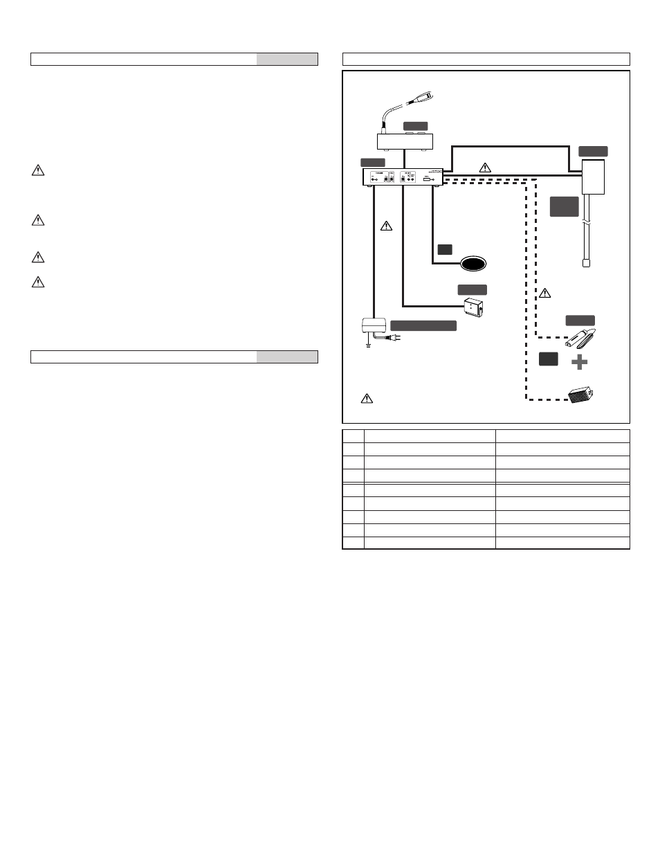
Wiring
1. Main unit MU-100
2. Operation unit OU-100
3. Gooseneck microphone IME-100
4. Driver unit DR-100
5. Acoustic I/O tube AI-100 and acoustic tube IAX-100
6. Power supply adapter PS-2420UL/2420S
7. Sensor ISE-100
8. Paging speaker (option)
Suitable paging speakers have 4 to 6
Ω impedance and rated
input of 3W or more, with a maximum input of 6W or more.
[1] Special connection cord for operation unit and main unit
(approximately 2m,6'6").
Be sure to insert the cables to the correct polarity.
[2] Microphone cable: Ø0.65 mm (22AWG) to 1.2 mm (16AWG)
2-conductor shielded cable
Be sure to insulate the joints of the cable.
[3] Speaker cable: Ø0.9 mm (19AWG) to 1.2 mm (16AWG) cable
Be sure to insulate the cable splices.
[4] Wire Clamp
[5] Connection cord (approximately 3.5m, 11'5")
Wiring distance
5-2
English
Cable layout
1. Use the special cable provided with the operation unit to
connect the operation unit with the main unit.
2. Receive input microphone cable layout
• Use a 2-conductor shielded cable with a high shielding effect.
• Splice the cable from the microphone to the terminal block on
the main unit.
• Be sure to splice the cable with the correct polarity.
3. Transmit output speaker cable layout
• Use a cable of Ø0.9 mm (19AWG) specification or more.
• Splice the cable from the speaker to the terminal block of the
main unit.
• A twisted pair cable is suitable for the speaker.
• Be sure to splice the cable with the correct polarity.
5-3
Ø0.65~1.2 mm
AWG22~AWG16
A
20 m (max.)
66'(max.)
A'
20 m (max.)
66'(max.)
D
20 m (max.)
66'(max.)
Ø0.9~1.2 mm
AWG19~AWG16
B
20 m (max.)
66'(max.)
B'
20 m (max.)
66'(max.)
C
20 m (max.)
66'(max.)
E
20 m (max.)
66'(max.)
Page Speaker
MU-100
OU-100
DR-100
AI-100
IAX-100
PS-2420UL / 2420S
IME-150
ISE-100
External Speaker
C
A (Mic)
A' (Mic)
B (Speaker)
D
E
OP
OP
B' (Speaker)
: Use the shield cable.