Cab003 – 1978-1987 g-body, Www.bmrfabrication.com – BMR Suspension CAB003 User Manual
Page 2
G-BODY CONTROL ARM RELOCATION BRACKETS
CAB003 – 1978-1987 G-BODY
CONTINUED
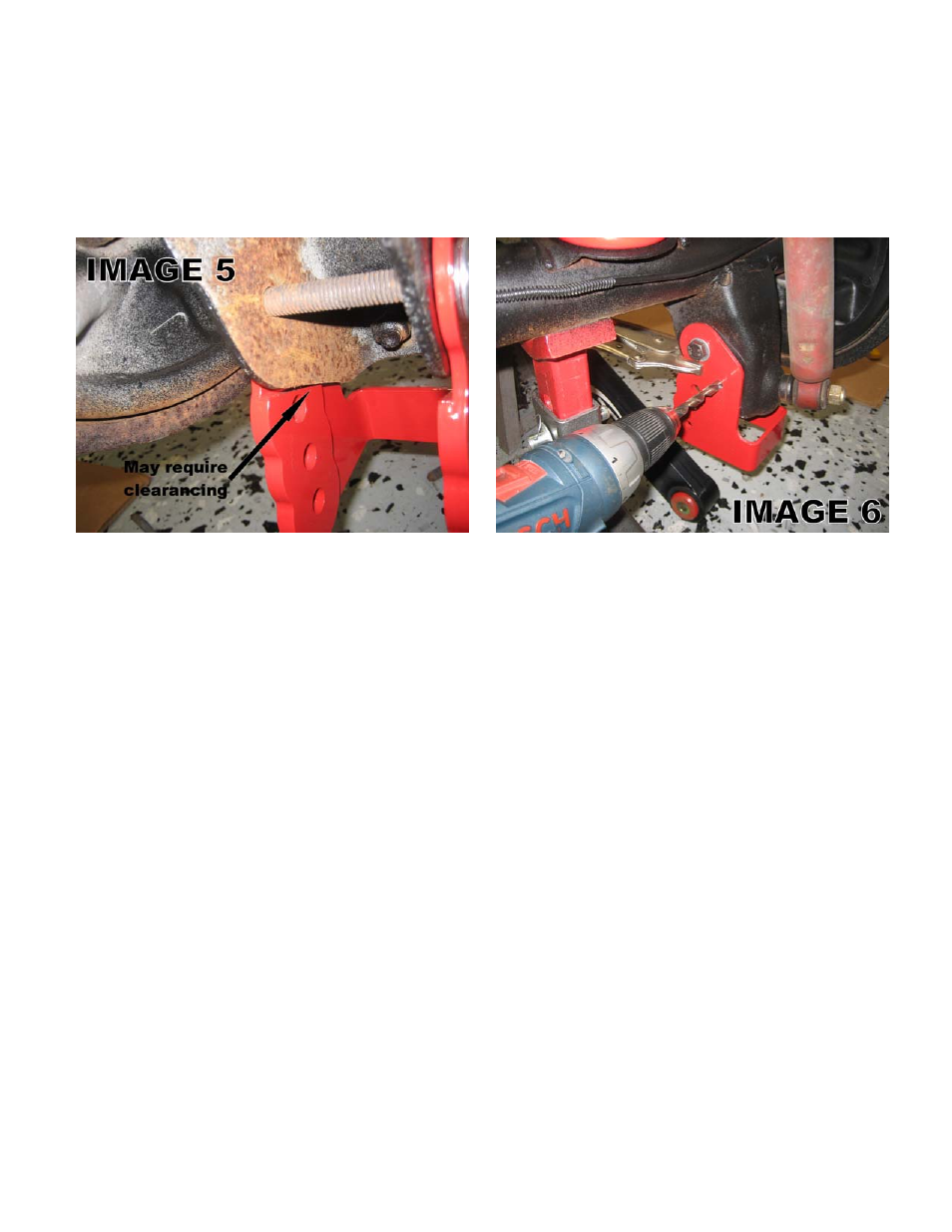
7. Position an angle-finder on the backside of the bracket as shown in Image 4 on the previous page. Rotate the bracket until it
is at 90 degrees. NOTE: this angle should be exactly 90 degrees different from the control arm angle to provide the most
accurate positioning and insure side-to-side equality. Due to manufacturer’s production variance, it may be necessary to
grind additional clearance on the factory control arm mount in order to allow the BMR relocation bracket to be positioned
properly. See Image 5.
8. Once the bracket is accurately positioned to 90 degrees, tighten the cross-bolt to prevent it from moving or clamp it in place
with a set of vise grips.
9. Using the hole in the BMR relocation bracket as a drill guide, drill a 3/8” hole through the factory control arm mount.
(Image 6)
NOTE: It is not necessary to drill the hole in the outer side of the bracket however it can be done if desired and additional bolts are
provided. Drilling from the outside is not possible without removing the axles, brake assembly and brake backing plate. Drilling
straight through from the inside to the other side is very difficult but can be done with a little patience. It is simpler to begin with a
smaller size drill bit, ¼” or 5/16”. Slide the drill-bit through the existing hole and up against the outer side of the mount. Sight the
drill from the back and the top (or bottom) to verify that the drill is positioned as close as possible to the hole on the other side. Drill
this “pilot hole” first. With any luck, you should come through the existing hole in the other side of the bracket. If not, you will have
to try again until the bit comes through the existing hole. Once through, switch back to the 3/8” bit and begin drilling. As the bit
begins to come through the other side, the existing hole will attempt to “self-align” the drill bit until the bit is through both sides of the
bracket.
10. If you will not be welding the brackets into position, proceed to step 12. If welding, remove the bracket and sand off the
powdercoat in the areas to be welded. Prep the rear end in the weld areas then re-install the bracket, inserting and tightening
the bolts to verify proper positioning. Weld at least 3 inches of weld per side of the bracket.
11. Remove the bolts, wire wheel the welds and paint with a rust preventative sealer.
12. Insert the supplied 3/8” bolts from the inside of the bracket then thread the washers and self-locking nuts onto them. Tighten
to 40 ft/lbs. Tighten the 12mm cross-bolt to 75 ft/lbs.
13. Raise the control arm up to the desired mounting hole and insert the supplied 12mm bolt, washer and nut. Tighten to 75
ft/lbs.
14. Repeat steps 4-13 for the other side control arm bracket.
15. Re-install the wheels/tires. Lower vehicle.
WWW.BMRFABRICATION.COM
This product is an aftermarket accessory and not designed by the vehicles manufacturer for use on this vehicle. As such, buyer assumes all risk of
any damage caused to vehicle/person during installation or use of this product.
2