Rear upper control arm bushing bk017 (continued) – BMR Suspension BK017 User Manual
Page 3
Rear Upper Control Arm Bushing
BK017 (Continued)
10.
Using a 21mm socket, remove the 4
cradle mounting bolts. See Image 7 on the
previous page. Lower the cradle
approximately 2-3 inches.
11.
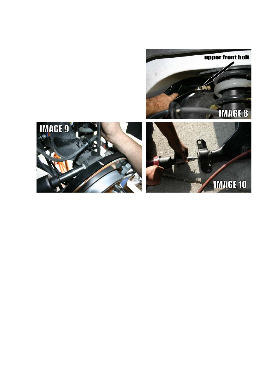
Using a 21mm wrench and 21mm
socket, remove the inner front bolt on the
upper control arm. See Image 8 to the right.
12.
Using an 18mm wrench and 18mm socket, remove the outer bolt on the upper control arm.
Image 9 above.
13.
Remove the two 18mm bolts at the rear of the upper control arm.
14.
Remove the upper control arm.
15.
Note the orientation of the rear bushing saddle on the control arm before removing the bushing.
Using a 21mm socket, remove the bushing retainer bolt as shown in Image 10 above.
16.
Using a hydraulic press, remove the OE bushing from the saddle.
17.
Position the bushing shell to match the original orientation then push the BMR bushing into the
shell with the flange of the bushing towards the outside of the A-arm. Insert the provided sleeve then
attach the assembly to the upper control arm. Place the provided washer over the bolt then tighten the
bolt to 130 ft/lbs. Re-install control arm using the OE mounting hardware. Torque the rear saddle bolts
to 85 ft/lbs. Torque the front inner mount to 130 ft/lbs. Torque the outer bolt to 85 ft/lbs.