Brewer AssistPRO User Manual
Page 6
Document # 101522 0608 REV A ER 784
6
Leveling the Table
A leveling screw pad (Figure 5) is located in six places
under the table’s base. Adjust the six leveling pads to
achieve a solid, level installation.
Installing the Power Cord
1. Remove the power cord from the shipping box.
2. Insert the plug end of the power cord into the recep-
tacle on the table (Figure 6). Make sure the plug end
shape is correctly oriented to the receptacle shape.
Installing the Foot Control
1. Remove the foot control from the shipping box.
2. Insert the end of the cord into the foot control recep-
tacle on the table (Figure 6). Make sure the tab on the
cord plug is aligned with the groove in the receptacle,
and the plug is fully seated.
3. Thread the locking collar onto the receptacle
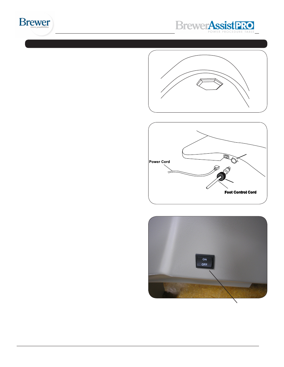
4. Make sure the on/off switch located on the backrest
shroud is turned to the “on” position. See figure 7.
5. Make sure both Safety On/Off Switches are on (lighted).
See figure 9.
6. Test the foot control for operation.
Figure 5. Leveling Screw Pad (located under table)
Figure 6. Power Cord & Foot Control Cord Receptacles
Figure 7
INSTALLATION (CONTINUED)
Locking Collar
Receptacle
Foot Control/Hand
Pendant On/Off
switch