Installation instructions, 3 install duct bracket and deflector, 2 install hood mounting screws – GE PV970NSS User Manual
Page 19
49-80549-2
19
3 INSTALL DUCT BRACKET AND
DEFLECTOR
The duct bracket should be installed against the back
ZDOODQGIOXVKZLWKWKHFHLOLQJWKHSRLQWZKHUHWKH
ceiling meets the wall should be level for the bracket
and duct cover to fit flush. This bracket will hold the
duct cover in place at the top.
Secure the bracket to the wall:
• Align the diamond centerline cutout on the bracket to
the penciled centerline on the wall.
• Mark 2 screw hole locations in the wall.
'ULOOµ
pilot holes in the marked locations.
• If pilot holes do not enter wood studs, enlarge the
KROHVWRµDQGLQVWDOOPHWDOZDOOIDVWHQHUDQFKRUV
(provided).
• If mounting directly to a masonry wall, obtain
appropriate #10 masonry screw anchors. Drill and
install per the fastener supplier’s instructions.
• Drive screws, by hand, into the fasteners to allow
DQFKRUVWRH[SDQG5HPRYHWKHVFUHZV
6HFXUHWKHEUDFNHWWRWKHZDOOZLWKZRRGVFUHZVDQG
or fasteners.
• Assemble the air deflector accessory to the
duct cover bracket with the 4 assembly screws
provided. DO NOT tighten screws. This is a temporary
installation.
Installation Instructions
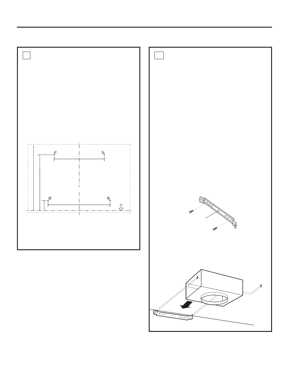
2 INSTALL HOOD MOUNTING SCREWS
The mounting screws must enter the horizontal
support or wall studs.
• With the template taped in place, use a punch to
mark mounting bracket screw locations.
'ULOOµSLORWKROHVLQRIWKHSXQFKHGORFDWLRQVLQ
the lower bracket. If the bottom 2 pilot holes do not
HQWHUZRRGHQODUJHWKHKROHVWRµDQGLQVWDOOPHWDO
wall fastener anchors (provided).
• Remove the template.
,QVWDOOWKHWRSPRXQWLQJVFUHZVOHDYHµJDS
between the screw head and the wall. This will allow
the keyhole slot on the hood frame to engage the
screw head.
IMPORTANT: Use the mounting screws provided.
DO NOT USE DRYWALL SCREWS.
• Check to be sure the mounting screws are
horizontally level.
Centerline cutout
REAR WALL
MOUNTING TEMPLATE
V
e
rt
ical
Centerline
ALIGN BOTTOM EDGE
WITH PENCIL LINE
INDICATING BOTTOM
OF THE HOOD
11-7/16"
Installation Height
Horizontal Line
CL
DRILL 2 (TWO) 3/16" PILOT HOLES THROUGH STUDS OR REAR WALL SUPPORT
10-1/8"
12-08 JR
2"
DRILL 2 (TWO) 3/16" PILOT HOLES THROUGH STUDS OR REAR WALL SUPPORT
12-1/2"
WALL VENT IS 27-3/4" MIN.
ABOVE THE INSTALLATION
HEIGHT
31-14772 Printed in Mexico