Caution, Warning – GE PV970NSS User Manual
Page 16
16
49-80549-2
Installation Instructions
,167$//$7,21³9(17('727+(2876,'(
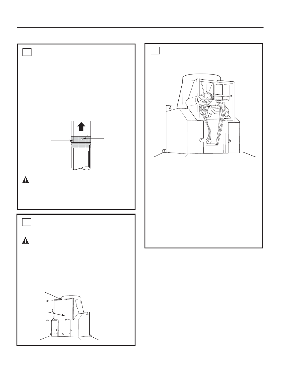
5 CONNECT DUCTWORK
• Remove shipping tape from the damper.
• Install ductwork, making connections in the
direction of airflow as illustrated.
3XVKGXFWRYHUWKHH[KDXVWRXWOHWDQGGDPSHU
• Secure joints in ductwork with sheet metal
screws.
• Wrap all duct joints and the flange connections
with aluminized duct tape for an airtight seal.
CAUTION:
Do not use sheet metal
screws at the hood flange connection. Doing
so will prevent proper damper operation. Seal
connection with tape only.
6 CONNECT ELECTRICAL
Verify that power is turned off at the source.
WARNING:
If house wiring is not 2-wire
with a ground wire, a ground must be provided by
the installer. When house wiring is aluminum, be
VXUHWRXVH8/DSSURYHGDQWLR[LGDQWFRPSRXQG
and aluminum-to-copper connectors.
• 5HPRYHWKHVFUHZVRQWKHMXQFWLRQER[FRYHU
and the knockout on the top left side.
Junction
ER[FRYHU
Knockout
Duct tape
over seam
and screw
Screw
Airflow
• 6HFXUHWKHKRXVHZLULQJWRWKHMXQFWLRQER[
with a strain relief (not provided).
• Connect the white lead to the branch circuit white
lead.
• Connect the black lead to the branch circuit black
lead.
&RQQHFWWKHJUHHQ\HOORZOHDGWRWKHEUDQFK
circuit green lead or bare ground lead.
• Secure all the connections with wire nuts on
each electrical connector.
3XVKWKHZLUHVLQWRWKHMXQFWLRQER[DQG
replace the cover. Be sure the wires are not
pinched.
• Secure the MXQFWLRQER[FRYHUZLWKthe 6
original screws.
6 CONNECT ELECTRICAL