System board switches – HP ProLiant DL385 G7 Server User Manual
Page 13
Component identification 13
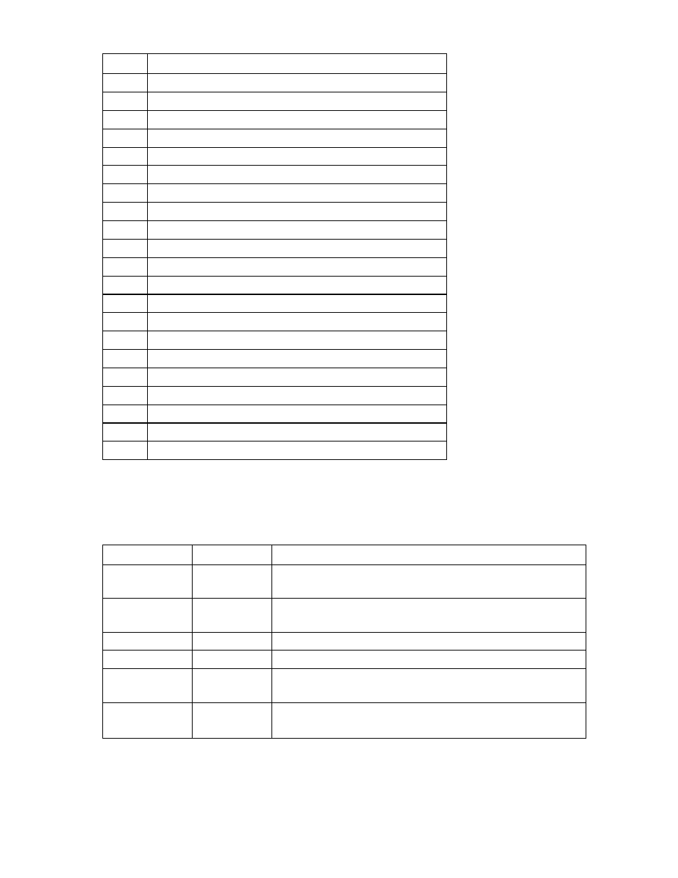
Item
Description
8
System battery connector
9
TPM connector
10
NMI jumper
11
Primary riser connector
12
SD card connector
13
Secondary riser connector
14
Secondary SAS power connector
15
Primary SAS power connector
16
Diagnostics LEDs
17
Primary SAS data connector
18
Secondary SAS data connector
19
SAS cache connector
20
Fan 1 connector
21
Processor 1 memory sockets
22
Fan 2 connector
23
Fan 3 connector
24
Fan 4 connector
25
Processor 1 socket
26
Fan 5 connector
27
Processor 2 socket
28
Fan 6 connector
*Connect the USB tape power connector to the secondary SAS power connector.
System board switches
System maintenance switch
Position
Default
Function
S1
Off
Off = iLO 3 security is enabled.
On = iLO 3 security is disabled.
S2
Off
Off = System configuration can be changed.
On = System configuration is locked.
S3
Off
Reserved
S4
Off
Reserved
S5
Off
Off = Power-on password is enabled.
On = Power-on password is disabled.
S6
Off
Off = No function
On = ROM reads system configuration as invalid.
When the system maintenance switch position 6 is set to the On position, the system is prepared to erase
all system configuration settings from both CMOS and NVRAM.