Figure 3-2, Writeread buffer structure for read operation, Figure 3-3 – HP Integrity NonStop H-Series User Manual
Page 22: Writeread buffer structure for write operation
Interfacing With the Open SCSI I/O Process (IOP)
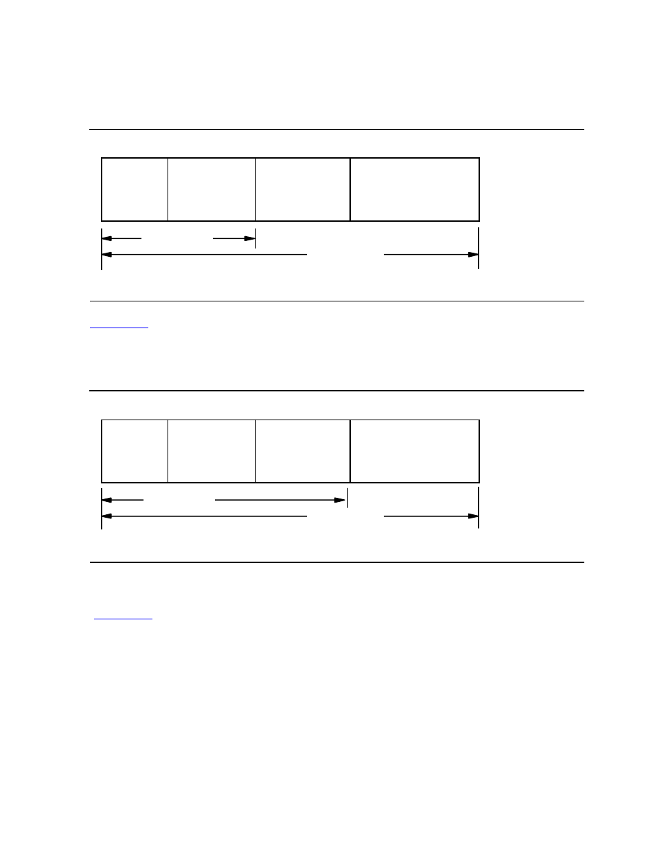
Structure of the WRITEREAD Buffer
CCB. However, the application reads back the entire buffer, which contains the header
block, the updated CCB, and both the sense buffer and data buffer, which now contain
information.
shows an example of the read count and write count for an operation that
writes data to a device. In this example, the amount of data written to the IOP requires
the entire buffer, but the application reads back just the header block, the updated
CCB, and the contents of the sense buffer if it was specified.
One way to minimize the amount of data transferred between an application and an
IOP is for the sense buffer to follow the CCB whenever the sense buffer is specified
(
), so that it is not necessary to transfer an empty buffer just to get sense
information. If the application does not need the data it is writing after it is written (the
application is not writing the same data multiple times to the device), the sense buffer
could use the same offset as the data buffer and thus overwrite the data that was
written to the device. This mechanism should not be used when reading from a device
because both the data buffer and sense buffer might be returned from the device and
the data for one would overwrite the data for the other.
Figure 3-2. WRITEREAD Buffer Structure for Read Operation
Figure 3-3. WRITEREAD Buffer Structure for Write Operation
Header
Block
CCB
Sense Buffer
(optional)
Data Buffer
(optional)
Read Count
007
CDT
.CDD
Write Count
Header
Block
CCB
Sense Buffer
(optional)
Data Buffer
(optional)
Write Count
008
CDT
.CDD
Read Count