Structure of the writeread buffer, Figure 3-1, Writeread buffer structure – HP Integrity NonStop H-Series User Manual
Page 21
Interfacing With the Open SCSI I/O Process (IOP)
Structure of the WRITEREAD Buffer
Structure of the WRITEREAD Buffer
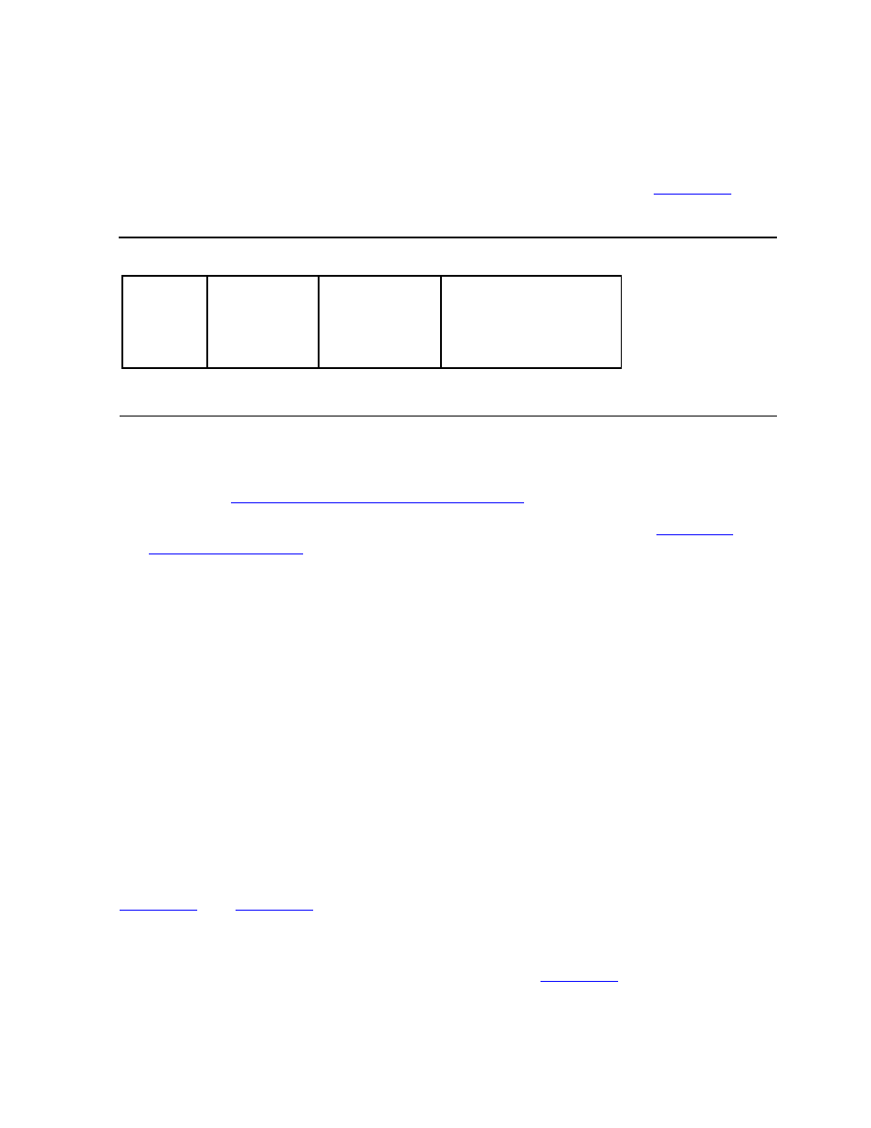
The buffer passed to and returned from the WRITEREAD procedure contains a header
block, a control field whose structure corresponds to that of a CAM control block
(CCB), an optional sense-buffer field, and an optional data-buffer field.
shows the basic layout of the buffer.
These rules apply to formatting the buffer:
•
The header block must be the first field in the buffer. For details about the header
block, see
The WRITEREAD Buffer Header Block
•
The second field must be the CCB. For details about the CCB, see
•
The sense-buffer and data-buffer fields are included if required by the specified
operation.
The existence, location, and length of the sense buffer and data buffer are specified by
fields within the CCB when the specified operation is the CAM operation Execute SCSI
I/O.
The sense buffer is optional, but it should usually be present so that sense information
can be returned when a check condition occurs on the device.
The data buffer must be present when a SCSI operation transfers data to or from the
device.
In normal operation, an application or driver sets up the header block and CCB,
making provision for any data that is to be transferred in either direction. The
WRITEREAD operation transfers the buffer to the IOP, which executes the operation,
updates the CCB, fills in the sense buffer and data buffer as needed, and returns as
much of the buffer to the application as the
read-count
parameter permits. (See
To minimize the number of empty bytes copied through the message system with each
WRITEREAD operation, set the
read-count
and
write-count
parameters of
WRITEREAD so that empty buffers are not transferred.
shows an example
of the read count and write count for an operation that reads data from a device. In this
example, the amount of data written to the IOP contains only the header block and
Figure 3-1. WRITEREAD Buffer Structure
Header
Block
CCB
Sense Buffer
(optional)
Data Buffer
(optional)
006
CDT
.CDD