Removing the bracket screws – HP PCIe U320 SCSI Host Bus Adapter User Manual
Page 15
The last device in the bus — that farthest from the adapter — must be properly terminated for each
SCSI bus. When planning device termination, keep the following in mind:
• Use an LVD terminator if you are only using LVD devices.
Although you can use a Single-Ended terminator, all devices will be limited to Ultra SCSI speeds and
cable lengths. Single-Ended devices require a Single-Ended terminator. If you use an LVD terminator
with Single-Ended devices, the system may hang or devices may not be seen on the SCSI bus. Some
termination manufacturers provide automatically sensing terminators.
• LVD Ultra2 and Ultra160 SCSI devices cannot supply their own termination.
• Wide (16-bit) and narrow (8-bit) devices can be connected together on the same connector of the
host adapter card, but wide devices must be attached first, followed by narrow devices.
To terminate the SCSI bus, the cable or adapter used to convert from a wide (68-pin) connector to
a narrow (50-pin) connector provides partial termination, allowing the upper 8-bits (or byte) of the
wide SCSI bus to be properly terminated. A narrow terminator should be used on the last narrow
device to terminate the rest of the SCSI bus. A SCSI bus without partial termination between the
wide and narrow devices may at first appear to work correctly, but occasional I/O errors occur
without proper termination.
• Termination power: Host adapters supply termination power to the bus at all times and many
SCSI devices are also able to supply termination power. SCSI signal quality, particularly with long
or marginal quality cables, may be improved if the device supplies the termination power. See
your device documentation for information on your device's ability to supply termination power.
3.
Review system documentation to select an appropriate slot to install the adapter.
The combined power consumption of the expansion slots must not exceed the limits for your system.
If you have more than one expansion card installed, ensure power consumption is within the limits
outlined for your system.
4.
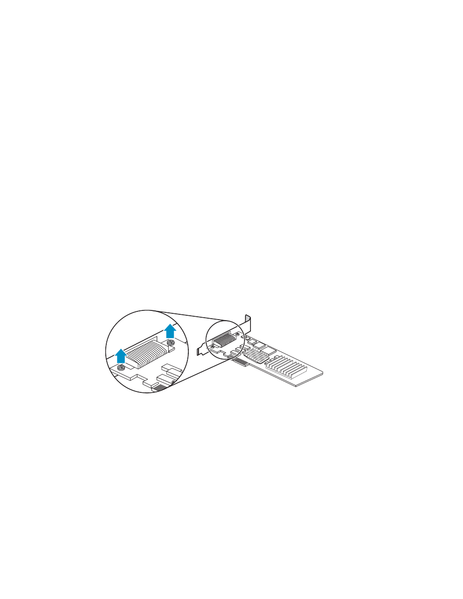
If the selected installation slot is low profile, replace the mounting bracket on the adapter.
a.
Remove the two screws on top of the board that secure the bracket to the board, as shown in
11314
Figure 2 Removing the bracket screws
User guide
15