ALESIS ANDROMEDA A6 User Manual
Page 126
Chapter 5: Oscillators and Filters
124
A
NDROMEDA
A6 R
EFERENCE
M
ANUAL
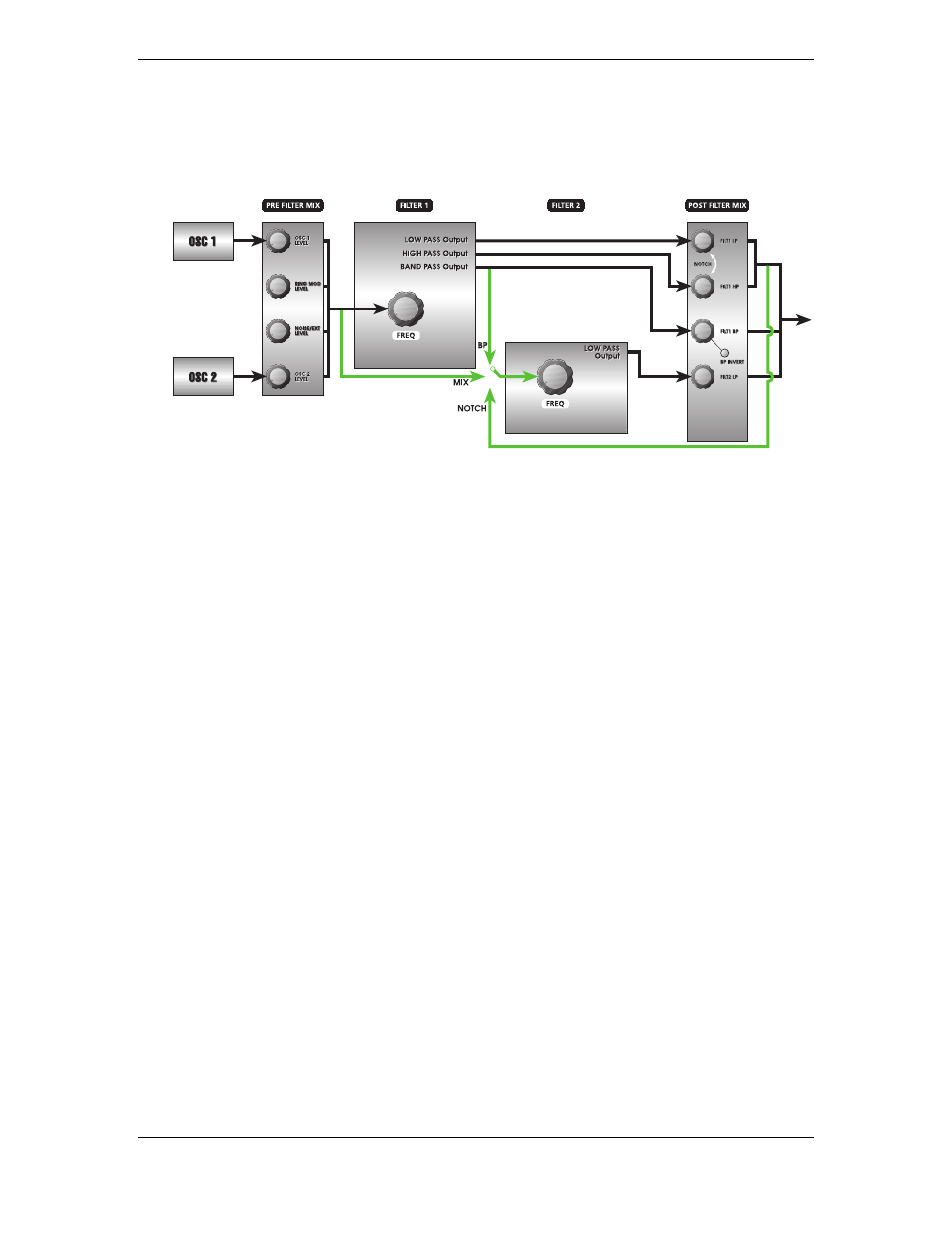
4. The composite output of the
PRE FILTER MIX
, the Band Pass output of
FILTER 1
or the Notch output of the of the
POST FILTER MIX
can be selected as the input
of
FILTER 2
for additional 4-pole low pass filtering.
The
F2 INPUT
button is used to route these signals into
FILTER 2
. Pressing this
button repeatedly switches between
MIX
,
NOTCH
,
BP,
or nothing as the input to
FILTER 2
:
•
When
MIX
is selected, the source of
FILTER 2
is the
PRE FILTER MIX
—the
oscillators, ring mod and Noise. This is the same signal that goes to
FILTER 1
.
So when
MIX
is used, you have both a 2-pole multi-mode filter (
FILTER 1
) and
a 4-pole low-pass filter (
FILTER 2
) operating in parallel.
This provides unprecedented capabilities in analog filtering. You now have
the ability to route the same signal to two independent VCFs – with identical
or different modulations.
•
When
NOTCH
is selected, two things happen:
•
the source of
FILTER 2
is only the notch-filtered output of
FILTER 1
(which
is the post-fader sum of Filter 1's low-pass and high-pass sections)
•
and those two volume controls of Filter 1 are disconnected from a direct
connection to the VCA.
In other words, when
NOTCH
is used, you have two parts of a multi-mode
filter (
FILTER 1
) and a 4-pole low-pass filter (
FILTER 2
) connected in series.
Note that you won't hear any output from
FILTER 2
unless either or both of
Filter 1's
HIGH PASS
or
LOW PASS
knobs are up. Only the
BAND PASS
knob will
send audio from Filter 1 directly to the VCA on its own.
In this case "notch" is a relative term, assuming that both the knobs are up. If
the
HIGH PASS
knob is turned fully counter-clockwise, the notch effect is
defeated and the low-pass output of
FILTER 1
is left as the signal. By the same
token, if the
LOW PASS
knob is turned fully counter-clockwise instead, the
notch effect is also defeated but the high-pass output of
FILTER 1
remains.
So, in essence, the
NOTCH
function can also be considered a low-pass or high-
pass input from
FILTER 1
, depending on how the
LOW PASS
or
HIGH PASS
knobs are set.
•
When
BP
is selected, only the band-pass output of
FILTER 1
is input to
FILTER
2
. Unlike NOTCH mode, however, the
FILTER 1 BAND PASS
volume control